Week 8 - BlockMesh Drill down challenge
Aim : The aim of the given challenge is to use the OpenFoam to generate the given geometry, apply the suitable boundary conditions, create a accurate mesh and run the simulation succesfully.
Given geometry:
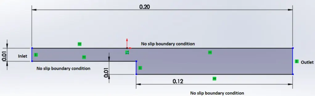
There are three important steps to run any simulation using OpenFoam:
1) Pre processing: We define the desired gemoetry of the region. further the flow region of geometry is divided into subdivisions of smaller domains called grid or mesh.we also define the physical phenomenon with appropriate boundary conditions.
2)Solver: We will only focus on the finite volume method, as it is central to the most well-established CFD solvers. In outline, the finite volume method consists of the following steps:
1. Integration of the conservation of mass, energy and momentum equations over
all the control volumes in the domain
2. Discretization – conversion of the resulting integral equations into a system of
algebraic equations
3. Solution of the algebraic equations by an iterative method
3)Post processing: This is where you take a look at the results and visualize them so that you can see
what happens in your model. Typical elements of post-processing are:
Definition of suitable cutting planes for visualization
Contour plots of properties/flow variables
Vector plots
Streamlines
Line plots
Balances
for the given problem we are using openfoam tool called paraFoam to visualize the solution geometry.
Solution:
1) we copy the cavity folder from icofoam folder in incomprissible flow tutuorial to our run directory.
2)further the blockmeshdict in systems is modified to generate the given geometry.similarly we also change the 0 directory in order to provide initial conditions of pressure and velocity in the given case.
3) the conctroldict is used to store the simulation time.The time from where simulation starts (startFrom), the time when the simulation finishes (stopAt), the time step (deltaT), the data saving interval (writeInterval), the saved data file format (writeFormat), the saved file data precision (writePrecision), and also if changing the files during the run can affect the run or not (runTimeModifiable) are set in this file. we have taken o startFrom and run the simuation for 0.3 sec stopAt.
4)After editing the four files i.e. the blockmeshdict,0directory(p and U) and the controlDict its time to run the blockMesh command to check the mesh geometry if the mesh is succesfully generated then we type in the name of solver to run the simulation in this case it is icoFoam.
5) the final step is to visulaize the geometry for that we have made use of inbuilt command ParaFoam which shows the opens your simulation in paraview.
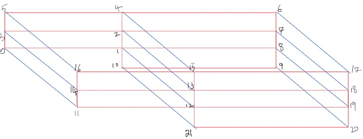
blockmeshDict file:
/*--------------------------------*- C++ -*----------------------------------*\
 ========= |
 \\ / F ield | OpenFOAM: The Open Source CFD Toolbox
 \\ / O peration | Website: https://openfoam.org
 \\ / A nd | Version: 8
 \\/ M anipulation |
\*---------------------------------------------------------------------------*/
FoamFile
{
 version 2.0;
 format ascii;
 class dictionary;
 object blockMeshDict;
}
// * * * * * * * * * * * * * * * * * * * * * * * * * * * * * * * * * * * * * //
convertToMeters 0.01;
vertices
(
 (0 0 0)//vert0
 (8 0 0)//vert1
 (8 0.5 0)//vert2
 (0 0.5 0)//vert3
 (8 1 0)//vert4
 (0 1 0)//vert5
 (20 1 0)//vert6
 (20 0.5 0)//vert7
 (20 0 0)//vert8
 (20 -1 0)//vert9
 (8 -1 0)//vert10
 (0 0 0.1)//vert11
 (8 0 0.1)//vert12
 (8 0.5 0.1)//vert13
 (0 0.5 0.1)//vert14
 (8 1 0.1)//vert15
 (0 1 0.1)//vert16
 (20 1 0.1)//vert17
 (20 0.5 0.1)//vert18
 (20 0 0.1)//vert19
 (20 -1 0.1)//vert20
 (8 -1 0.1)//vert21
);
blocks
(
 hex (0 1 2 3 11 12 13 14) (200 10 1) simpleGrading (1 1 1)
 hex (3 2 4 5 14 13 15 16) (200 10 1) simpleGrading (1 1 1)
 hex (2 7 6 4 13 18 17 15 ) (200 10 1) simpleGrading (1 1 1)
 hex (1 8 7 2 12 19 18 13) (200 10 1) simpleGrading (1 1 1)
 hex (10 9 8 1 21 20 19 12) (200 10 1) simpleGrading (1 1 1)
);
edges
(
);
boundary
(
 inlet
 {
 type wall;
 faces
 (
 (0 11 14 3)
 (3 14 16 5)
);
 }
 outlet
 {
 type wall;
 faces
 (
 (9 8 19 20)
 (8 7 18 19)
 (7 6 17 18)
 );
 }
 frontAndBack
 {
 type empty;
 faces
 (
 (11 12 13 14)//front
 (14 13 15 16)
 (13 18 17 15)
 (12 19 18 13)
 (21 20 19 12)
 (0 3 2 1)//back
 (3 5 4 2)
 (2 4 6 7)
 (1 2 7 8)
 (10 1 8 9)
 );
 }
 noSlipWall
 {
 type wall;
 faces
 (
 (5 16 15 4)//top
 (4 15 17 6)
 (10 21 12 1)//step side
 (11 0 1 12)//bottom1
 (21 10 9 20)//bottom5
 );
 }
);
mergePatchPairs
(
);
// ************************************************************************* //
Pressure Boundary condition File:
/*--------------------------------*- C++ -*----------------------------------*\
 ========= |
 \\ / F ield | OpenFOAM: The Open Source CFD Toolbox
 \\ / O peration | Website: https://openfoam.org
 \\ / A nd | Version: 8
 \\/ M anipulation |
\*---------------------------------------------------------------------------*/
FoamFile
{
 version 2.0;
 format ascii;
 class volScalarField;
 object p;
}
// * * * * * * * * * * * * * * * * * * * * * * * * * * * * * * * * * * * * * //
dimensions [0 2 -2 0 0 0 0];
internalField uniform 0;
boundaryField
{
 inlet
 {
 type zeroGradient;
 }
 outlet
 {
 type fixedValue;
 value uniform 0;
 }
 frontAndBack
 {
 type empty;
 }
 noSlipWall
 {
 type zeroGradient;
 }
}
// ************************************************************************* //
Velocity Boundary Condition File:
/*--------------------------------*- C++ -*----------------------------------*\
 ========= |
 \\ / F ield | OpenFOAM: The Open Source CFD Toolbox
 \\ / O peration | Website: https://openfoam.org
 \\ / A nd | Version: 8
 \\/ M anipulation |
\*---------------------------------------------------------------------------*/
FoamFile
{
 version 2.0;
 format ascii;
 class volVectorField;
 object U;
}
// * * * * * * * * * * * * * * * * * * * * * * * * * * * * * * * * * * * * * //
dimensions [0 1 -1 0 0 0 0];
internalField uniform (0 0 0);
boundaryField
{
 inlet
 {
 type fixedValue;
 value uniform (1 0 0);
 }
 outlet
 {
 type zeroGradient;
 }
 frontAndBack
 {
 type empty;
 }
 noSlipWall
 {
 type noSlip;
 }
}
// ************************************************************************* //
Controldict File:
/*--------------------------------*- C++ -*----------------------------------*\
 ========= |
 \\ / F ield | OpenFOAM: The Open Source CFD Toolbox
 \\ / O peration | Website: https://openfoam.org
 \\ / A nd | Version: 8
 \\/ M anipulation |
\*---------------------------------------------------------------------------*/
FoamFile
{
 version 2.0;
 format ascii;
 class dictionary;
 location "system";
 object controlDict;
}
// * * * * * * * * * * * * * * * * * * * * * * * * * * * * * * * * * * * * * //
application icoFoam;
startFrom startTime;
startTime 0;
stopAt endTime;
endTime 0.3;
deltaT 0.00001;
writeControl timeStep;
writeInterval 20;
purgeWrite 0;
writeFormat ascii;
writePrecision 6;
writeCompression off;
timeFormat general;
timePrecision 6;
runTimeModifiable true;
// ************************************************************************* //
Output:
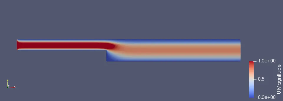
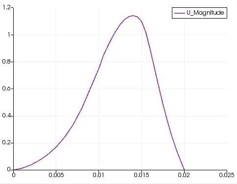
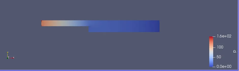
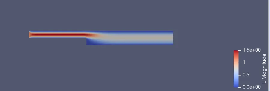
We have kept the controdict file and the 0dict file constant and only made changes in blockmesh file for the simplegrading part. as per the challenge we have taken simple grading factor 1,0.2,0.5 & 0.8
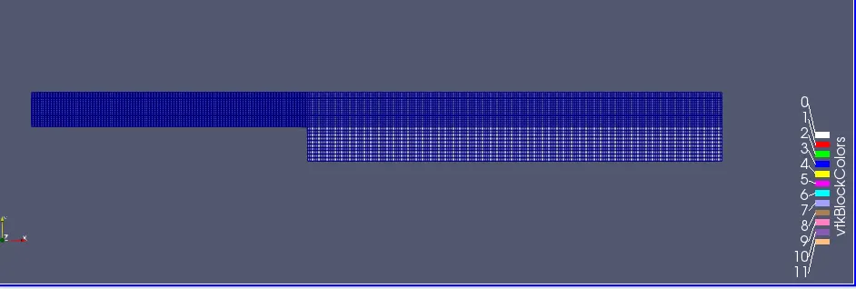
1)Mesh for geometry at grading factor 1:
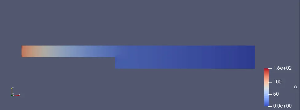
pressure variation daigram:
Velocity variation daigram:
Velocity profile at 0.085 m from inlet :
2) Mesh for geometry at grading factor 0.2:

pressure variation daigram:
Velocity variation daigram:
Velocity profile at 0.085m from inlet:
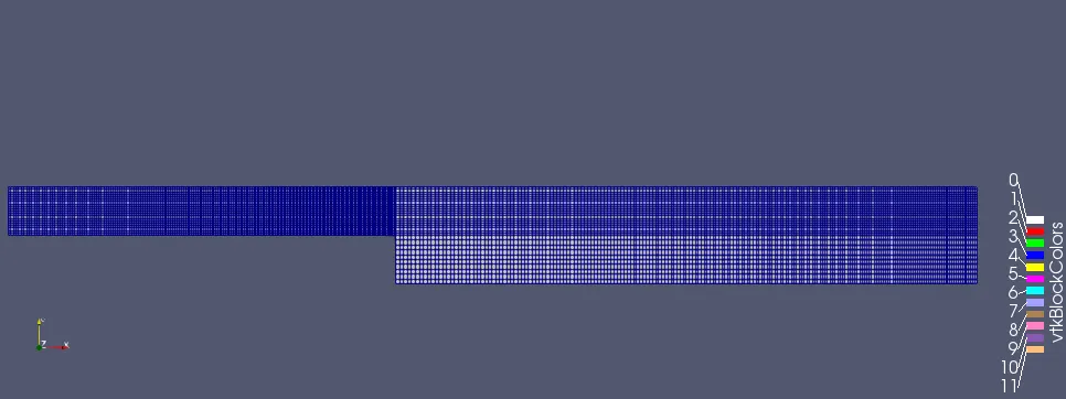
3) Mesh for geometry at grading factor 0.5:
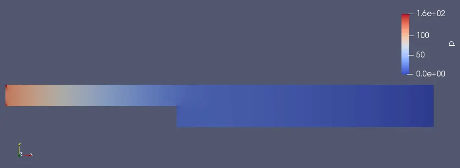
pressure variation daigram:
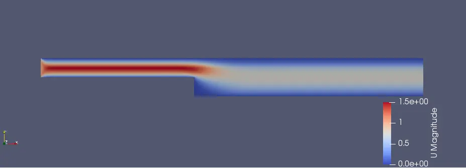
Velocity variation daigram:
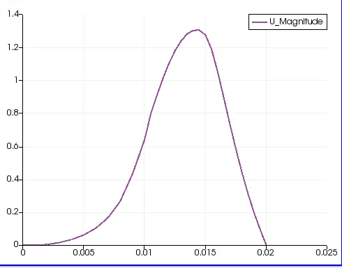
Variation of velocity profile at 0.085m form inlet:
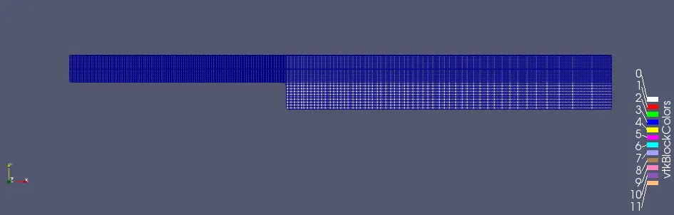
4) Mesh for geometry at grading factor 0.8:
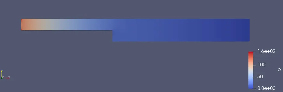
pressure variation daigram:
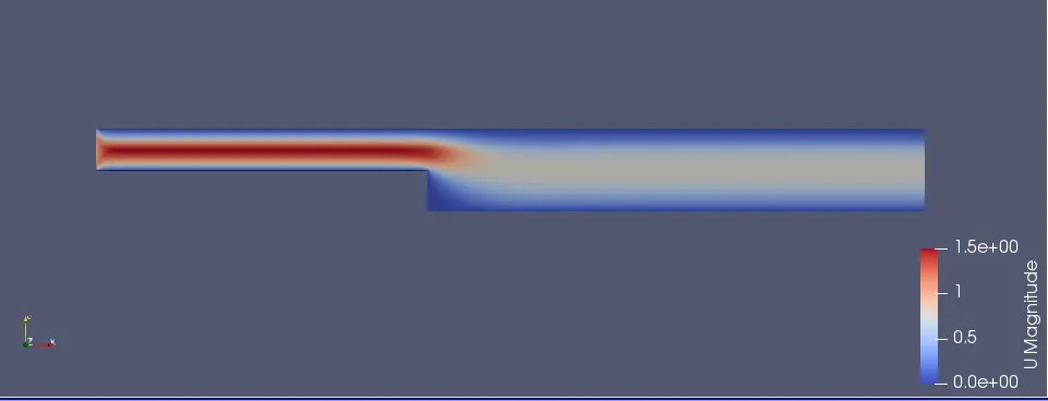
Velocity variation daigram:
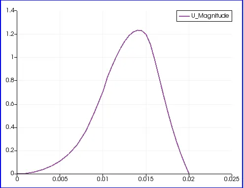
Velocity profile at 0.085m from inlet:
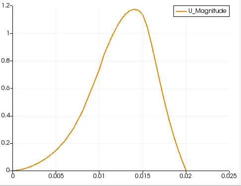
Conclusion:
As we have seen in above velocity variation profile for different grading factors we conclude that their is only a slight diffrence in profile for all the mesh grading but close look at the plot shows that lower grading factor gives finer mesh throughout the geometry hence velocity profile is more accurate with lower grading factor.