Week 9 - Parametric study on Gate valve.
Aim: To perform a parametric study on the gate valve simulation by setting the opening from 10% to 80%.
Gate valve:
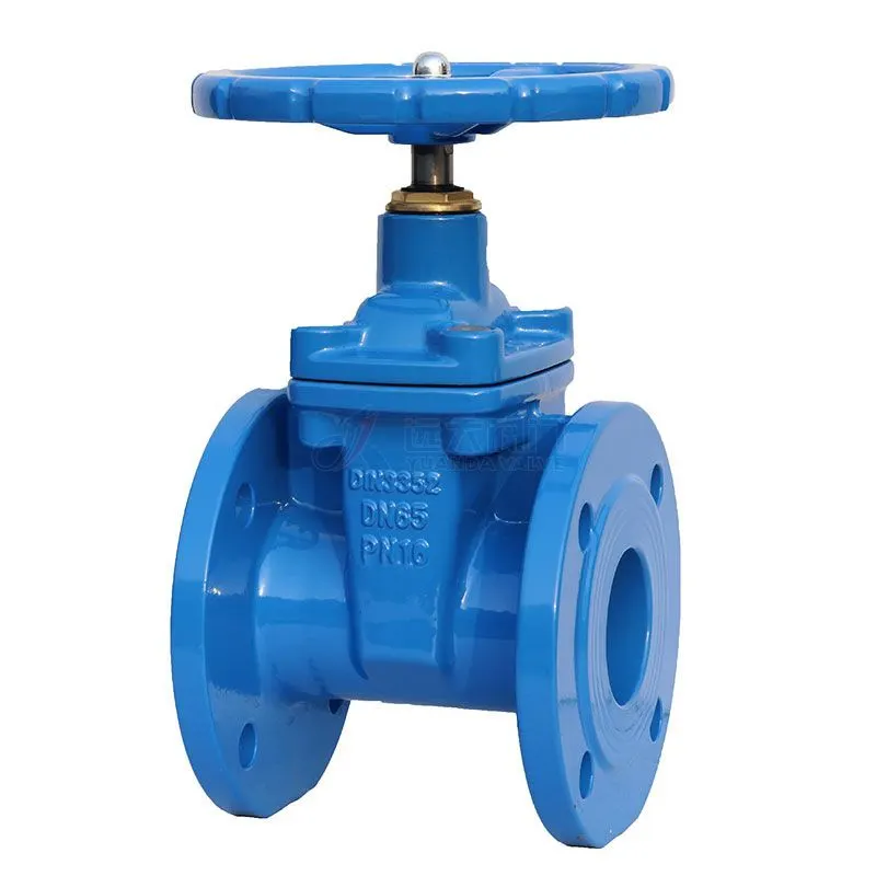
A gate valve, also known as a sluice valve, is a valve that opens by lifting a barrier (gate) out of the path of the fluid. Gate valves require very little space along the pipe axis and hardly restrict the flow of fluid when the gate is fully opened. The gate faces can be parallel but are most commonly wedge-shaped (in order to be able to apply pressure on the sealing surface).
Gate valves are used to shut off the flow of liquids rather than for flow regulation. When fully open, the typical gate valve has no obstruction in the flow path, resulting in very low flow resistance. The size of the open flow path generally varies in a nonlinear manner as the gate is moved. This means that the flow rate does not change evenly with stem travel. Depending on the construction, a partially open gate can vibrate from the fluid flow.
Flow coefficient:
The flow coefficient of a device is a relative measure of its efficiency at allowing fluid flow. It describes the relationship between the pressure drop across an orifice valve or other assembly and the corresponding flow rate.
Mathematically the flow coefficient Cv can be expressed as
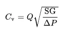
where:
Q is the rate of flow
SG is the specific gravity of the fluid (for water = 1),
ΔP is the pressure drop across the valve
Flow factor:
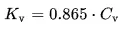
Kv can be calculated from Cv using the following equation
Solving & modelling approach:
Import the 3D gate valve geometry in space claim.
Use volume extract option to extract the fluid volume.
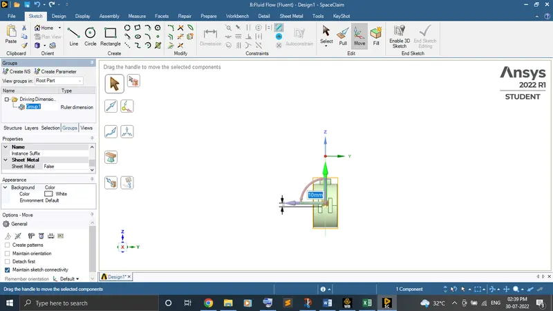
Open the gate valve for 10mm by using move option and create parameters by clicking on symbol P or go to the groups and create it.
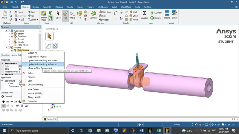
By keeping spindle and valve visible, right click the fluid volume and give “create the geometry for “
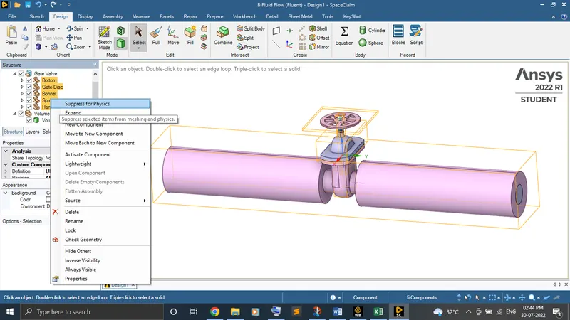
Use suppress for physics on whole geometry except fluid volume for not to take a part in meshing.
Load the geometry in meshing. Do the named selections for the inlet and outlet. Mesh the geometry for the default.
Do the necessary physics and boundary conditions setup in setup to converge the solution.
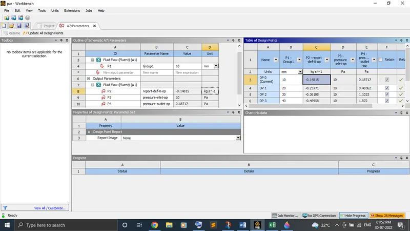
Go to the parameters. Now, create new design points from 20mm to 80mm to obtain the result for each lift of the gate valve.
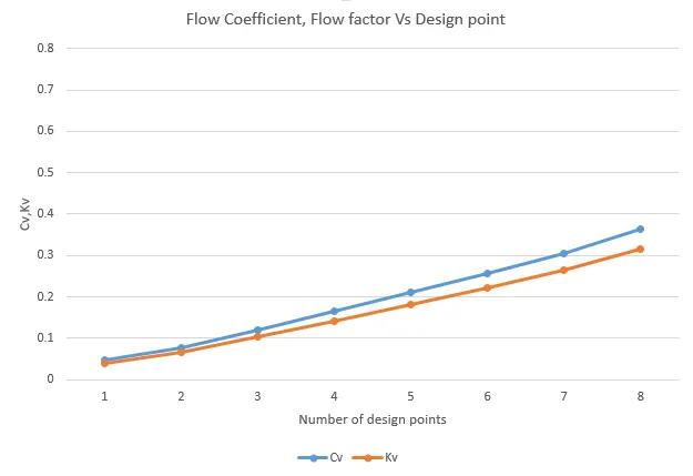
Finally, compare the result and plot the graph.
Pre-processing and solver setting:
Geometry:
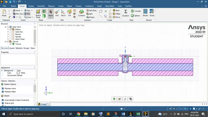
Import the 3D gate valve geometry in space claim.
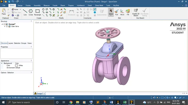
Use volume extract option to extract the fluid volume.
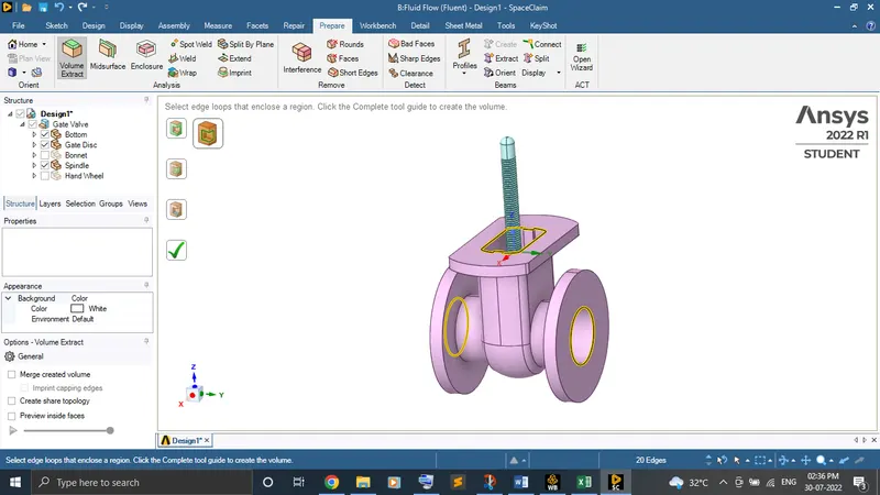
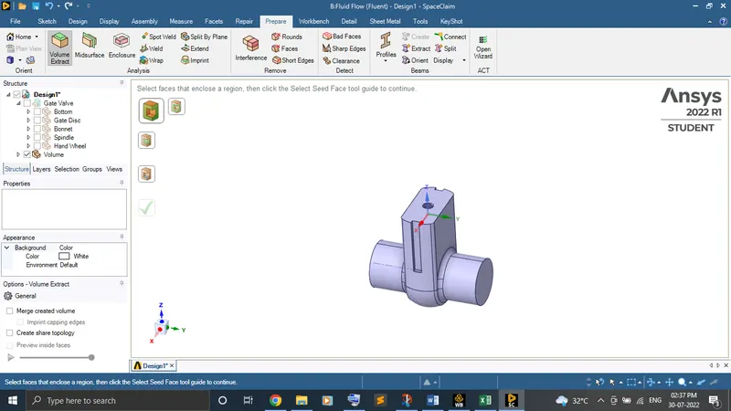
Lift the gate valve for 10mm by using move option and create parameters by clicking on symbol P or go to the groups and create it.
By keeping spindle and valve visible, right click the fluid volume and give “Update volume body in context “.
Use suppress for physics on whole geometry except fluid volume for not to take a part in meshing.
Meshing:
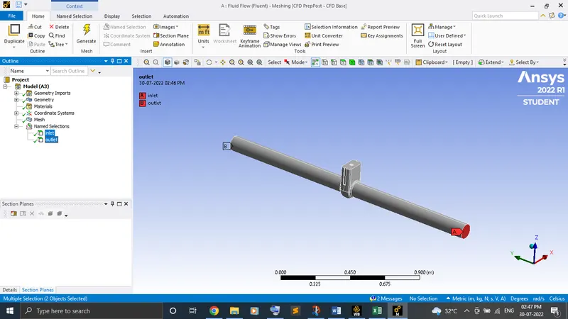
Load the geometry in meshing and do the named selections for the faces. Mesh the geometry for the default.
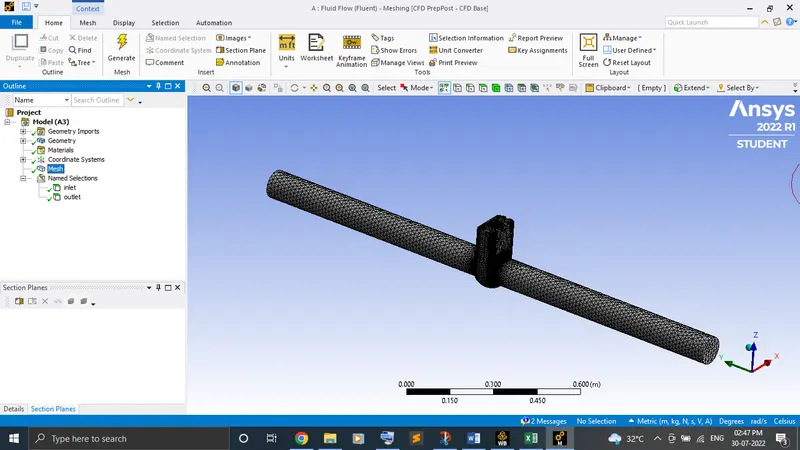
Nodes – 29099
Element - 137848
Setup:
Solver type - Steady state pressure based with gravity (z = -9.81 m/s2)
Model - Realizable, K-Epsilon viscous turbulence model with scalar wall treatment.
Material - Water-liquid
Boundary Conditions: Inlet (Pressure inlet) - 10 gauge pressure
Create the report definitions for mass flow rate from flux report to know the flow rate at outlet and mark the print to console & create output parameters to get the output result at the parameters tab. Repeat it for the pressure inlet & outlet.
Initialize the standard initialization from the inlet and run the calculation.
Parameters:
The negative flow rate indicates that the flow goes out through the outlet.
Result:

Conclusion:
From the result obtained, we can conclude that with the increase of the lift of the gate valve the pressure drop decreases. So, the velocity will be increase. With the increase of mass flow rate when gate valve lifts, the flow coefficient and flow factor also increases. Creating the parameters reduces the manual work and time.