Week 9 - Parametric study on Gate valve.
Aim:
To perform a parametric study on a gate valve at different valve opening settings.
Theory:
Gate valves work by inserting a rectangular gate or wedge into the path of a flowing fluid. They are operated by a threaded stem
which connects the actuator (generally a hand wheel or motor) to the stem of the gate. If the valve has a rising stem its position can
be seen just by looking at the position of the stem. A gate valve is used to control the fluid flow through lifting and descending the
gate. A gate distinct feature is to provide an unobstructed passageway, which includes minimal pressure loss over the valve.
Since there is no flow restriction while the gate is fully open, the pressure loss is rather small. The gate valve is typically entirely closed or fully open since a partly opened valve may vibrate and cause excessive wear. The body, seat, gate, stem, bonnet, and actuator make up a gate valve's essential parts. The main mechanism is simple: the handwheel is turned to raise and lower the gate using threads. To fully open the valve, they need to spin it more than 360 degrees.
Comparable in size and quality, gate valves are often slightly less expensive than ball valves. They are used in situations where valve activity is uncommon, such as isolating valves, and have a slower actuation than quarter-turn valves. Gate valves shouldn't be utilised to control flow; instead, they should be used completely open or fully closed. Manual gate valves are more economical since they are used less frequently than automated gate valves, which can have either an electric or pneumatic actuator. Gate valves are frequently used for many kinds of applications and can be installed above ground or below. They can handle the majority of fluids, including steam, water, oil, and gas, among others.
Part-1:
The handwheel, spindle, bonnet, and gate valve make up the solid geometry's bottom housing. The gate valve, which is manually operated by rotating the handwheel supported by the bonnet and connected via the spindle, limits the flow of fluid as it travels from the intake to the exit. The gate valve is lowered to restrict the mass flow of the fluid at the exit when a reduced mass flow is needed. It is necessary to model how the lift of the gate valve stopper affects the mass flow rate of the fluid at the exit.
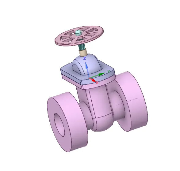
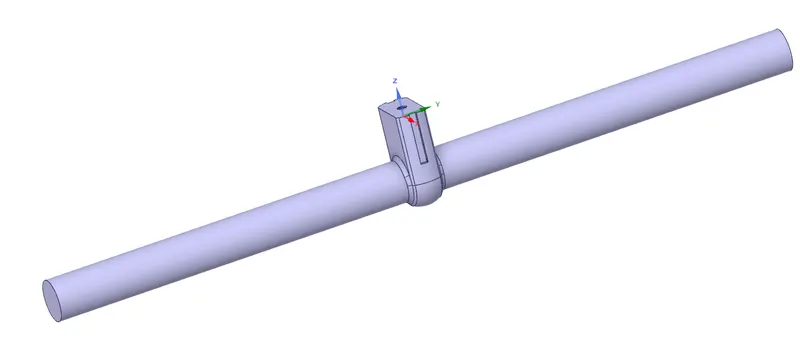
To simulate the effect of the stopper on the mass flow rate of the fluid at the outlet the stopper is moved 10mm in the positive Zdirection so that the flow path is partially open. This is parametrized. Next, the fluid is extracted from the solid geometry. The
parameterization helps us change its value and compute the required output parameters without having to repeat the same
processes again. Since we are not interested in the analysis of solid geometry, it is suppressed.
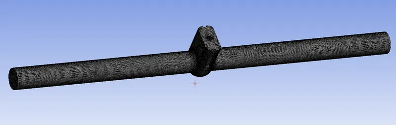
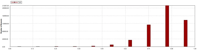
The meshing is finished when the geometry has been specified. The size of the mesh element used was 10mm. 101804 nodes and 508460 elements in total were formed once the necessary mesh was created.
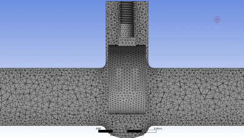
Resultant Mesh Quality ia as follows:
Water is the fluid medium. Gravitational acceleration is taken into account (along the negative Z-direction). The K-epsilon realisable turbulence model with scalable wall functions was utilised to tackle the issue using steady-state equations.
Pressure intake and pressure outlet defined the boundary conditions at the inlet and exit, respectively. At the intake and outflow, the gauge pressures are 10 Pascals and 0 Pascals, respectively. The calculated velocity was 0.1415488 m/s when standard initialization was performed from the intake.
To compute this attribute at various stopper sites, a flux report of mass flow rate is constructed and defined as an output parameter.
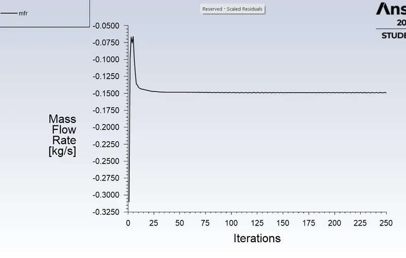
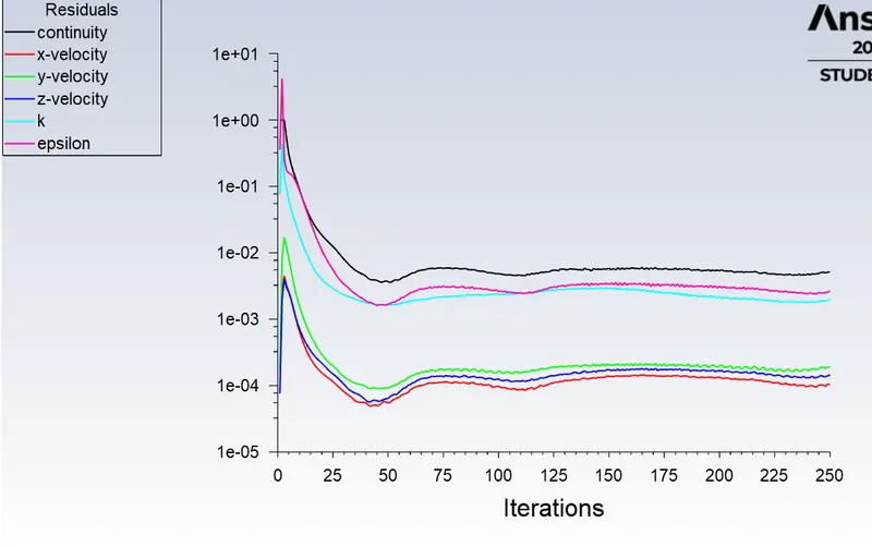
The solution was run for 250 iterations. and the residual plot is as follows
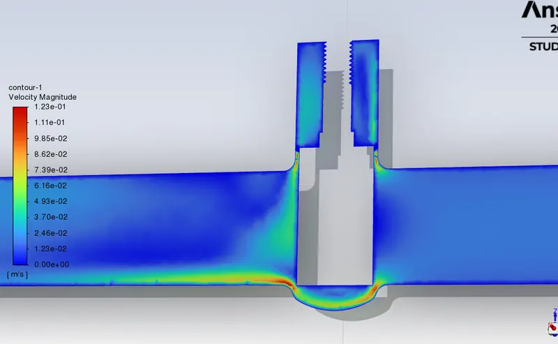
Next, we move on to the parameters tab to calculate the mass flow rates for the different stopper heights, and the following results
were obtained.
The mass flow rates' negative indications indicate that the fluid is leaving the domain. For stopper lifts between 10mm and 70mm, the mass flow rate is determined. With an increase in stopper light, the mass flow rate rises. The space available for the fluid to move expands as the stopper is progressively raised, increasing the mass flow. Ansys solves and calculates the output parameters when we run the parametric study, saving us time compared to if we had to do it manually. It does this by automatically changing the mesh to match the new geometry using the same mesh specifications as before.
Part-2:
A device's flow coefficient (Cv) is a measure of how effectively it allows fluid to flow. It explains the connection between the matching flow rate and the pressure drop via an orifice valve or other component.
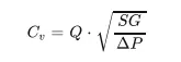
where Q is the flow rate (expressed in US gallons per minute)
The fluid's specific gravity is SG; water has a specific gravity of 1.
P is the valve's pressure drop (expressed in psi).
The metric equivalent flow factor(Kv) is calculated using metric units
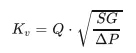
where Q is the flow rate (measured in m3/h).
The fluid's specific gravity is SG; water has a specific gravity of 1.
P is the valve's pressure drop (expressed in bar).
The formula is used to determine Kv from Cv.
Kv = 0.865 ⋅ Cv
The fluid's flow factor and flow coefficient at various valve displacement magnitudes are shown in the table below. The units must be changed to the precise units specified above before the parameters may be inserted into the formula.
| Valve Displacement | Mass flow rate (kg/sec) | Flow Factor(Kv) | Flow Coefficient (Cv) |
| 10 | -0.14951 | 53.82 | 62.21 |
| 20 | -0.24072 | 99.04 | 114.497 |
| 30 | -0.36189 | 130.28 | 150.612 |
| 40 | -0.47561 | 171.22 | 197.942 |
| 50 | -0.56597 | 203.75 | 235.549 |
| 60 | -0.64327 | 231.58 | 267.7225 |
| 70 | -0.71876 | 258.75 | 299.1329 |
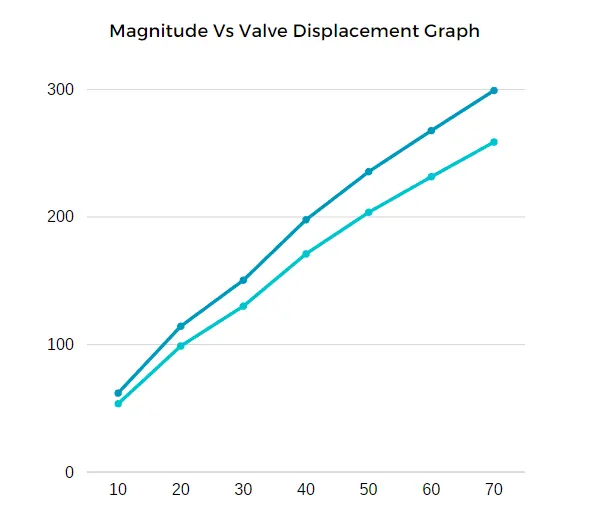
We may infer from the trend charts above that as the gate valve's opening grows, so does the mass flow rate.
The flow factor and coefficient rise together with the mass flow rate.
Conclusions:
1.You may define the parameter range, describe the design restrictions, and evaluate the effects of each parameter modification using parametric studies. You can assess your simulation once the settings have been produced. Until you are pleased with the outcomes, you can adjust the parameters or design limitations. You can promote a configuration back to the model as a CAD edit if you've decided that it meets your design requirements. You are asked if you want to make adjustments. The parametric study approach reduces the amount of time needed to run simulations that call for repeating the same processes for various conditions.
2.The following is necessary for a parametric study:
- Parametric Dimensions is the selected Design Objective.
- Nominated variables for the simulation
- Identified parameter ranges
- given design criteria
- Several variants were produced
3. The mass flow rate of the fluid and, consequently, the flow factor and flow coefficient rise when the valve stopping is progressively lifted, according to the parametric research of the gate valve.