Week 9 - Parametric study on Gate valve.
PROJECT REPORT
INTRODUCTION:
- Gate valves are used to control the flow of fluid through pipes
- When fully open typical gate valves give maximum fluid mass flow rate
- The outlet mass flow rate depends on the opening of the valve
- Depending on the construction, a partially open gate can vibrate from the fluid flow
GEOMETRY:
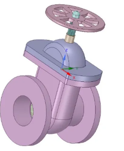
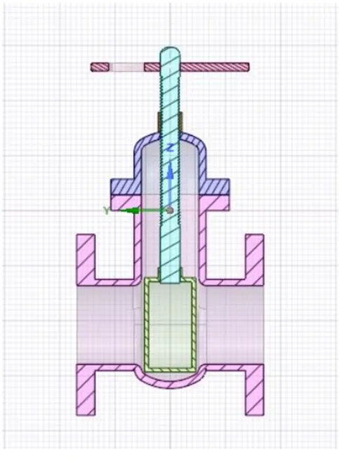
Given Geometry Section view
We need to make some modification to ensure the updating of geometry accordingly
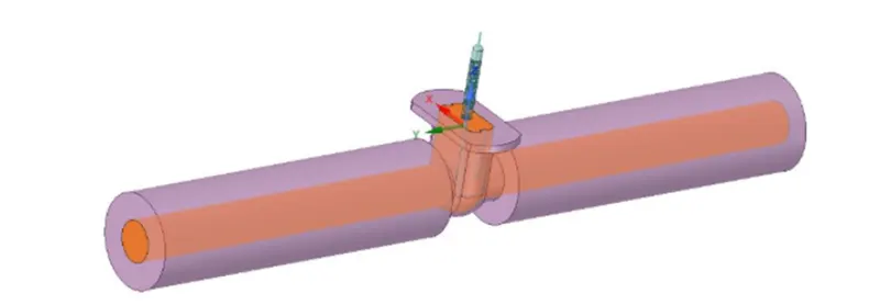
Fluid Volume
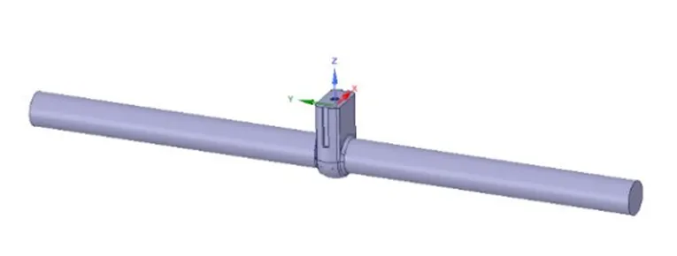
Updated geometry
We had to use pull option for updating the inlet and outlet, and we can use prepare option for volume extraction for fluid volume
After extracting the fluid volume, we are ready for meshing
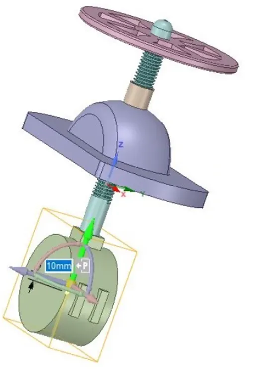
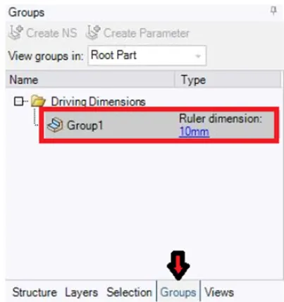
For setting the parameter we have to move the gate disc by different values to check the changes in the output
And we need to set a group for the parameter, by clicking on the create a parameter in group option and put a rural dimension as 10 for the first input
Mesh:
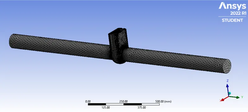
For meshing part, we are using a fine mesh with total elements of 135060
Nos
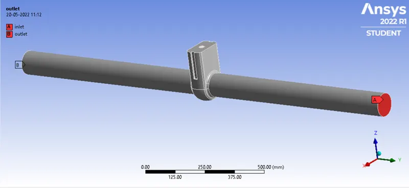
And after giving proper name selection as shown in the pic. We are ready for setup
SETUP:
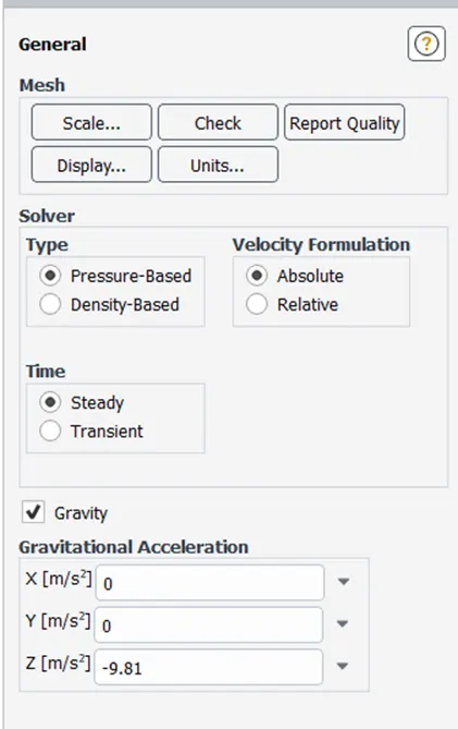
General setting:
Analysis type: steady state
Solver: Pressure base solver
Gravity: -9.81m/sq. s in -z direction
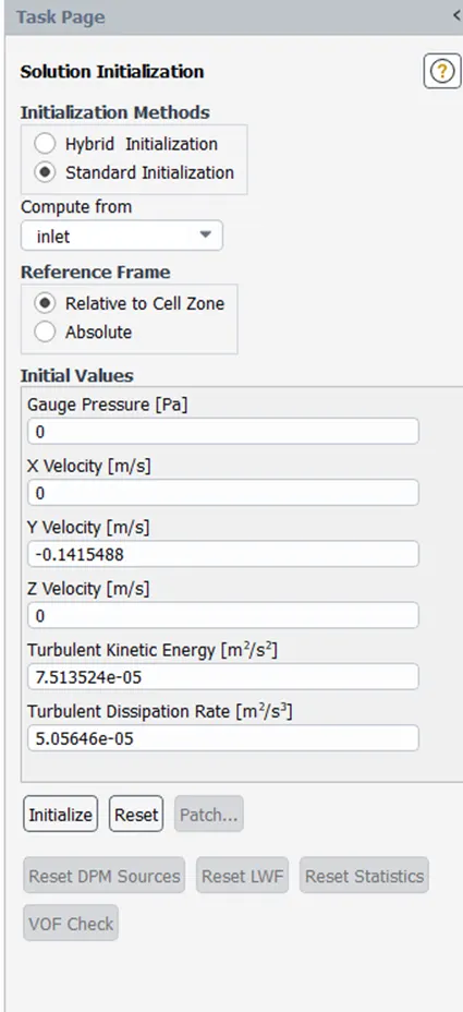
Viscouse model taken was K-epsilon model as the inlet was a pressure inlet and the inlet velocity is high so the character of the flow is turbulent
 .
.
Boundary condition
Inlet - Type – Pressure unlet
Gauge total pressure = 10Pa
Outlet- Type – Pressure outlet
Wall - Type – Wall
Condition - No Slip
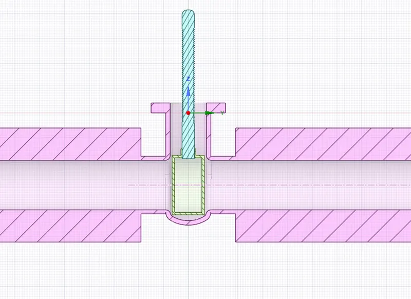
Initial close position
RESULTS:
Now for all the cases of disc from 10% to 80% one by one
- Flow coefficient
The flow coefficient of a device is a relative measure its efficiency at allowing fluid flow. It describes the relationship between the pressure drop across an orifice valve or other assembly and the corresponding flow rate.
Mathematically the flow coefficient Cv (or flow -capacity rating of valve) can be expressed as:
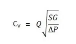
Where:
- Q is the rate of flow (expressed in US gallons per minute).
- SG is the specific gravity of the fluid (for water = 1)
- DP is the pressure drop across the valve (expressed is psi)
In more practical term, the flow coefficient Cv in the volume (in US Gallons) of water at 60 deg. F that will flow per minute through a valve with a pressure drop of 1 psi across the valve.
The use of the flow coefficient offers a standard method of comparing calve capacities and sizing valves for specific application that is widely accepted by industry.
Flow Factor:
The metric equivalent flow factor (Kv) is calculated using metric unit
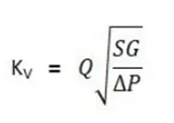
Where:
- Kv is the flow factor. Q is the flow rate
- SG is the specific gravity of the fluid (for water = 1)
- DP is the differential pressure across the device
Kv can be calculated from Cv using the equation as given below:
Kv = 0.865. Cv
The factor of valve indicates the water flow in m3/h, at a pressure drop across the valve of 1kgf/cm2 when the valve is completely open
Case 1:
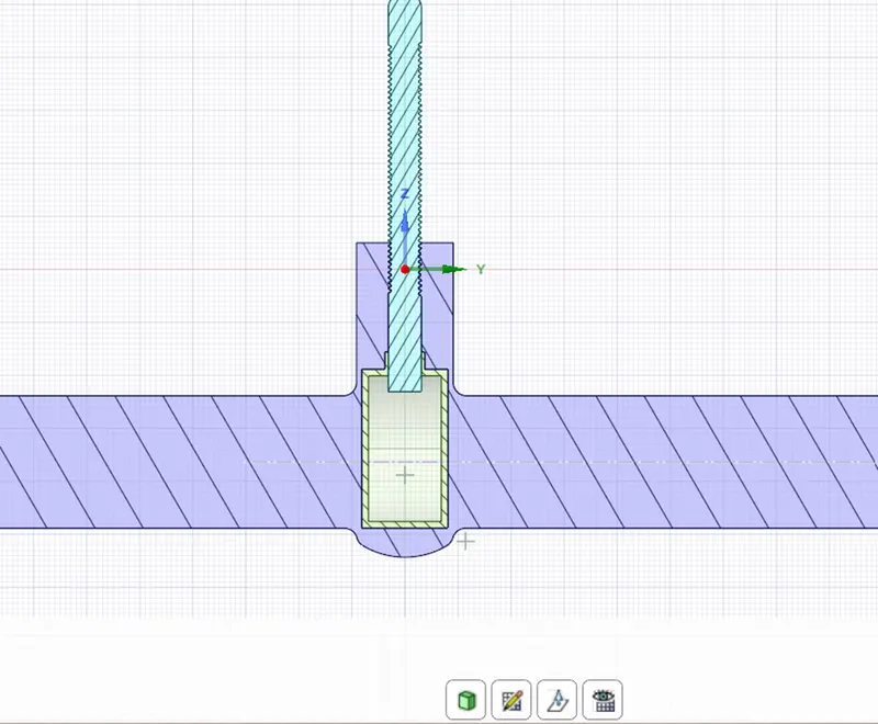
Valve open by 10mm
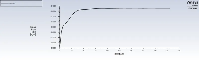
Mass flow rate
Residuals:
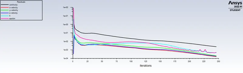
Here, the valve was open by 10mm and the mass flow rate at the outlet is 1.4974
Maximum velocity was around 0.145, avg. velocity of 0.096
Also, we can calculate the flow coefficient and the flow factor.
Q = 0.24096
SG = 1000/998.2 = 1
DP = pressure diff. = 7.32*10^-5
So, by above formula
Flow coefficient = 22.18
Flow factor = 19.81
Similarly for all the three cases as shown in below parameter chart we can calculate the values
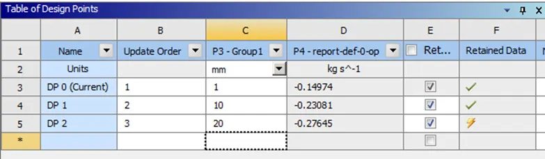
In the chart 1 represent 10mm as its an adjustment error in space claim
Similarly, 10 is 20mm and 20 is 30mm
VIDEO FILE LINK:
https://drive.google.com/drive/folders/1p80hJbB6H-6fo82dV-cw0Cgq_alAo4My?usp=sharing
After calculating the values, we get the following table:
|
GATE DISK HEIGHT ` |
MAXIMUM VELOCITY |
VELOCITY |
MASS FLOW RATE |
PRESSURE DROP |
FLOW COEFFICIENT |
FLOW FACTOR |
|
10 |
0.14 |
0.0966 |
0.148 |
7.32*10^-5 |
22.18 |
19.18 |
|
20 |
0.166 |
0.1106 |
0.2398 |
8.39*10^-5 |
26.19 |
22.61 |
|
30 |
0.192 |
0.128 |
0.2796 |
9.71*10^-5 |
36.66 |
27.11 |
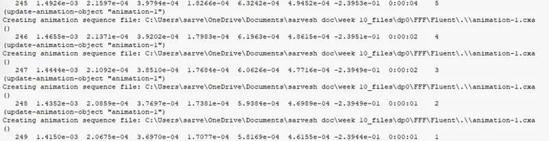
CONSOL FOR DISC HEIGHT 20MM
CONCLUSION:
- As the mass flow rate increases with the opening og gate valve disk, thus the fluid through the pipe will also increase
- as the gate disk opens the velocity increases and pressure drop decrease and therefore mass flow rate and flow coefficient increases.
- The flow coefficient is used to determine the valve size that eill best allow the valve to pass the requires flow rate which provide stable control of process fluid
- Due to high velocity and decrease in pressure drop there is formation of cavitation in the liquid system.