Week 8 - Simulation of a backward facing step in OpenFOAM
1) For GF value is 1, all cells are uniform through out
when grading factor is one the geometry becomes simple and the as the value of dx is ame throughout, the CFL value are same for entire block
though there is not any major difference in velocity flow throughout by changing GF but when we check the velocity plot it shows it is not as neat as when we use GF as 0.2, it shows that for minor detailing we should make our grin finer where the physics changes or where precise details are needed
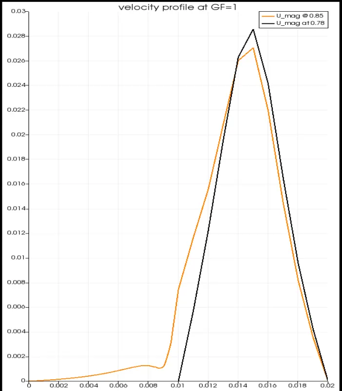
Flow chart is made on x=0.78 and x=0.85 as shown in graph leagends
As we can see if we dont use a finer grid the the chart is not that neat as the velocity is maximum in center and at edges it looses some velocity due to boundary layer
and the velocity drops after the step as the area increases so to keep the flow continuity the velocity decresses
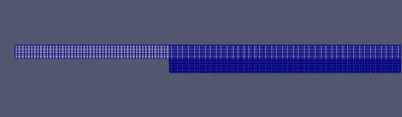

In velocity flow we can see the flow is not that detailed or specific as the grid are of same size but not finer at affected area,
though the flow is shown correctly
2) For GF value is 0.2
Now after making grid finer at the affected are we can see some changes in graph and flow dig.
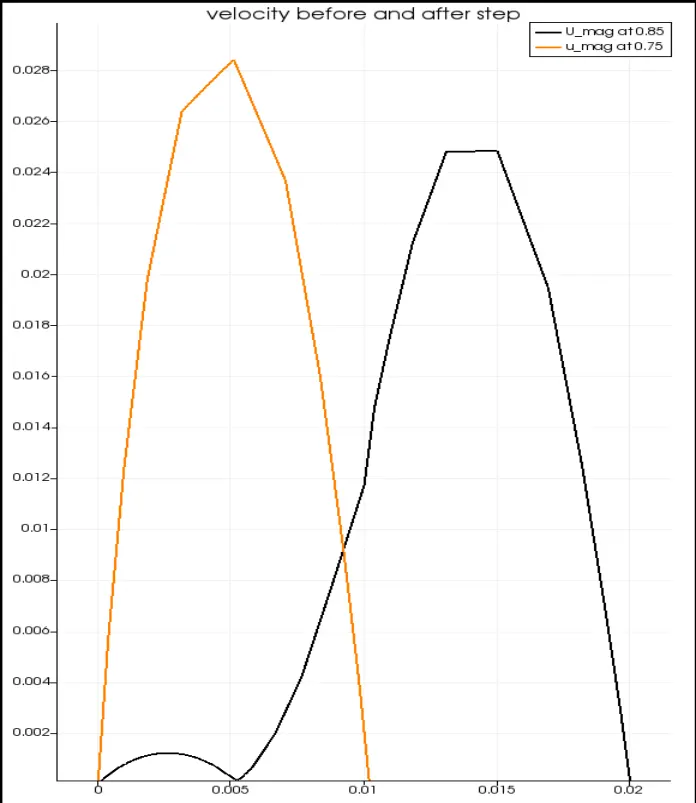
one plot is when x=0.75 and second plot is after the step i.e., x=0.85
Here, we can see the flow looks neater and in shape, the velocity is highest in centre part rather than walls, and the velocity decreases as the area increases


As here the grid was finer at the impact area, so the velocity graph can be cleaner and more precise,
also, in flow dig. the flow looks more Precise