Week 9 - Parametric study on Gate valve.
Aim :
To perform a parametric study on the gate valve simulation by setting the opening from 10 % to 80%.
Objective :
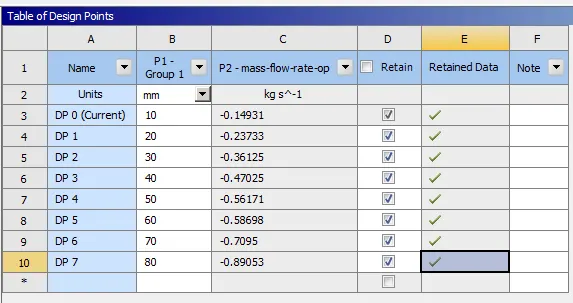
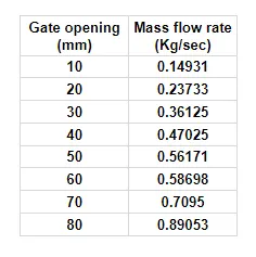
- Obtain the mass flow rates at the outlet for each design point.
- Calculate the flow coefficient and flow factor for each opening and plot the graph.
Theory :
Gate Valve :
- A gate valve can be defined as a type of valve that used a gate or wedge type disk and the disk moves perpendicular to flow to start or stop the fluid flow in piping.
- A gate valve is the most common type of valve used in any process plant. It is a linear motion valve used to start or stop fluid flow.
- In service, these valves are either in a fully open or fully closed position. The main function of the gate valve is to convert rotary motion to translation motion.
- Gate valves tend to be slightly cheaper than ball valves of the same size and quality. They are slower in actuation than quarter-turn valves and are for applications where valve operation is infrequent, such as isolating valves.
- Gate valves should be used either fully open or fully closed, not to regulate flow.
Parametric study :
- Parametric study as the name suggests is a type of study in which we vary the parameter to obtain the same results.
- Basically, this is a process of automating the process.
- If a user need to get an output results for varying a single parameter manually he have to vary the parameter in the design condition and the to re-mesh the volume and to carry out the initialization and the to fin the results this is automated by the use of parametric study.
Coefficient of Flow (`C_v`) :
`C_v =Q*sqrt((SG)/(DeltaP))`
Q = massflow rate (gallons/min)
SG = Spceific gravity
`DeltaP`= Pressure difference = `P_(out)-P_(In)` in psi
Flow Factor (`K_v`) :
`K_v =Q*sqrt((SG)/(DeltaP))`
Q = Massflow rate in m^3/hr.
`DeltaP`= Pressure difference = `P_(out)-P_(In)` in bar
But ,
`K_v = 0.865 * C_v`
Solving and modelling approach :
Geometry :
- The geometry file was imported onto Work bench Spaceclaim
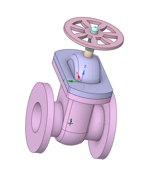
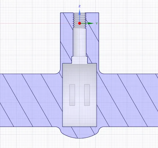
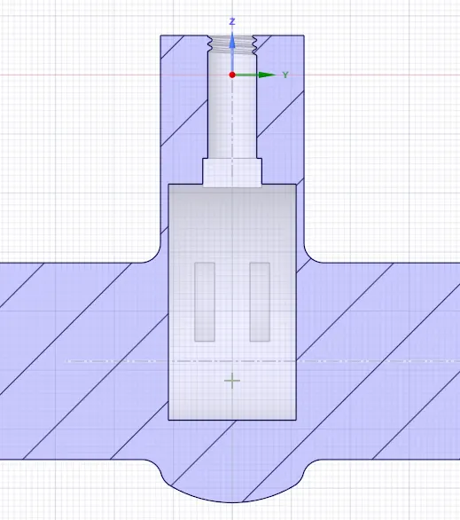
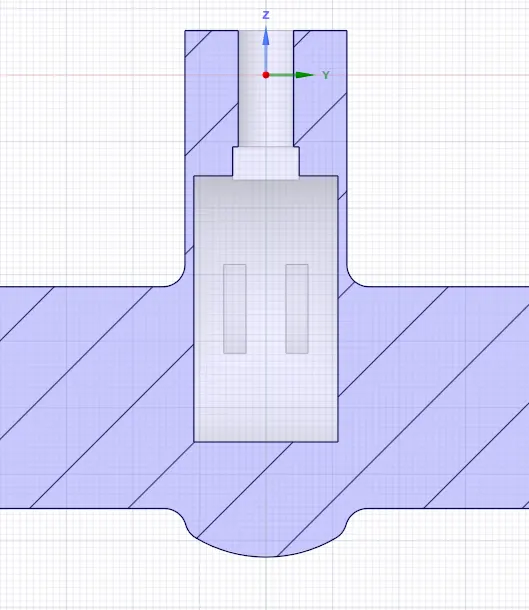
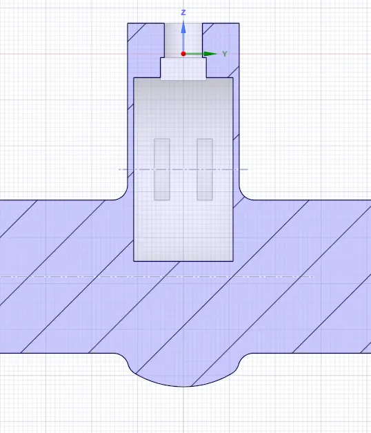
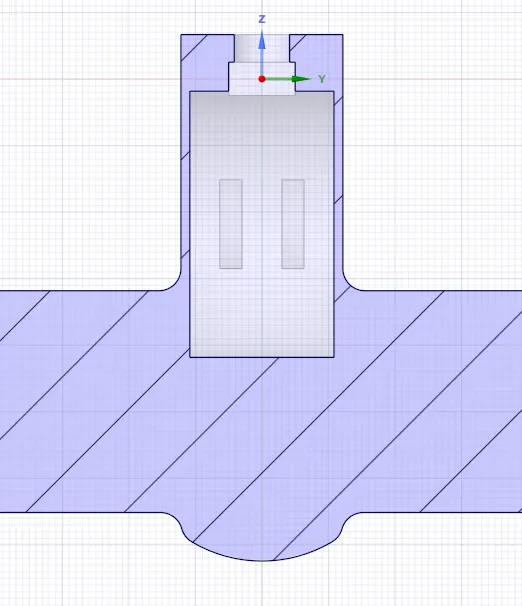
- Now, the move option was selcted to move the gate valve disk and spindle to a specified distance in y direction.
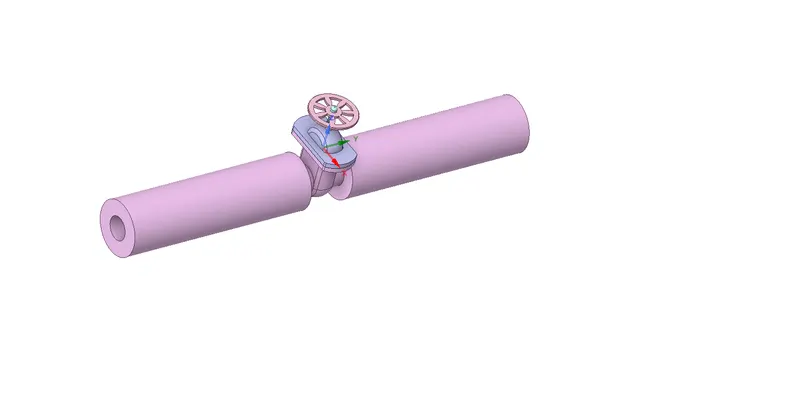
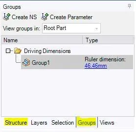
- As shown in the image the Create Parameter “P” does not appear along the dimension of the lift, the alternate way to parametrize the same is to go to the Groups menu which is adjacent to the Structure menu; In the Group menu, you will able to see the Create Parameter button, which will be enabled only after you have moved the gate disc, click on the Create Parameter following which you will see a Group-1 appear in which you can edit the dimensions of the lift. This will have parameterized your Gate Disc lift, you confirm the same by checking your workbench.
- Then the Volume of fluid was extracted by using 'volume extraction'.
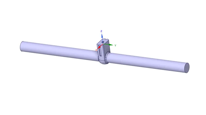
- Now all other components was suppressed for physics.
Meshing :
- Create the named selection as inlet and oulet.
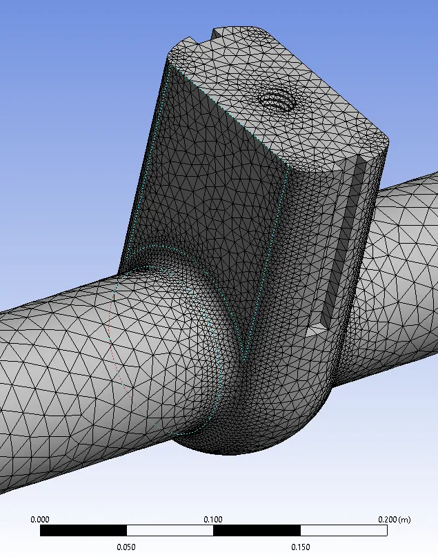
- Generate mesh using default mesh size.
No. of elements = 136250
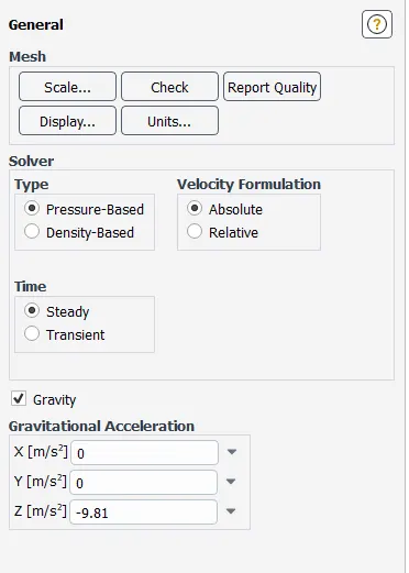
Fluent setup :
- General
- Viscous model

- Create Material : water-liquid and select material as water in cell zone. Then delete air from materials to avoid mixing.
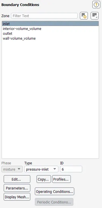
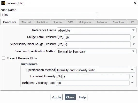
- Boundary conditions :
- Report defination
For mass flow rate

- Initialize the model using standard initialization
Results :
Cases :
| Disc Lift (mm) | Design point(Dp) |
| 10 | DP 0 |
| 20 | DP 1 |
| 30 | DP 2 |
| 40 | DP 3 |
| 50 | DP 4 |
| 60 | DP 5 |
| 70 | DP 6 |
| 80 | DP 7 |
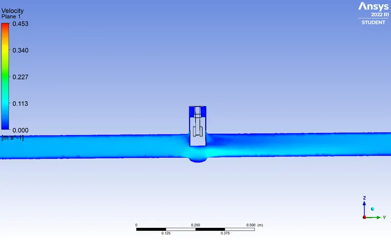
CASE 1 :
Gate disc lift : 10mm (10%)
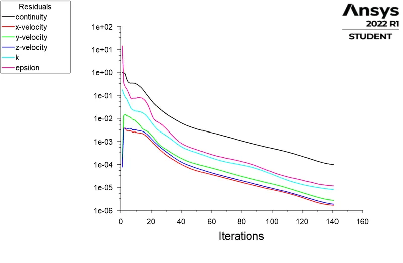
Residuals :
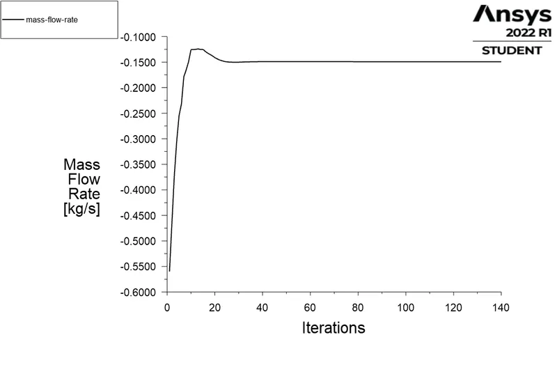
Mass flow rate :
Velocity contour :
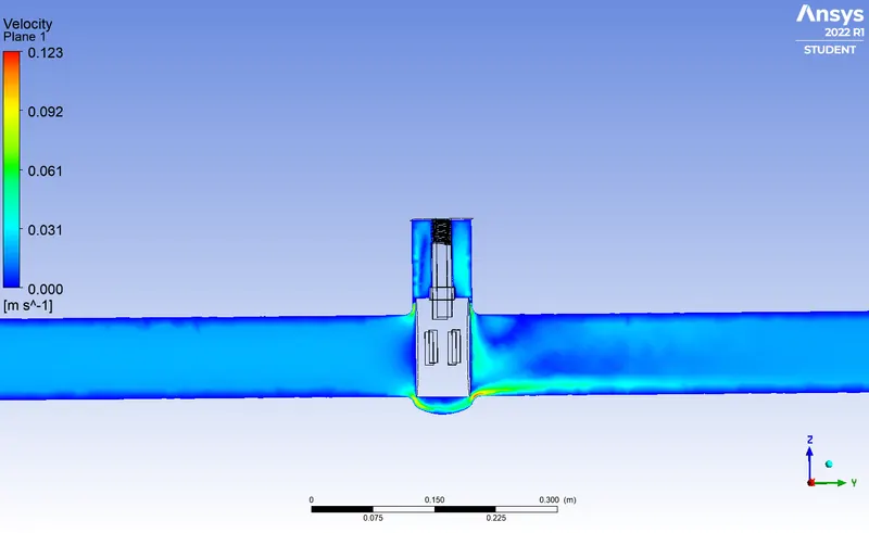
Case 2 :
Gate disc lift : 20mm (20%)
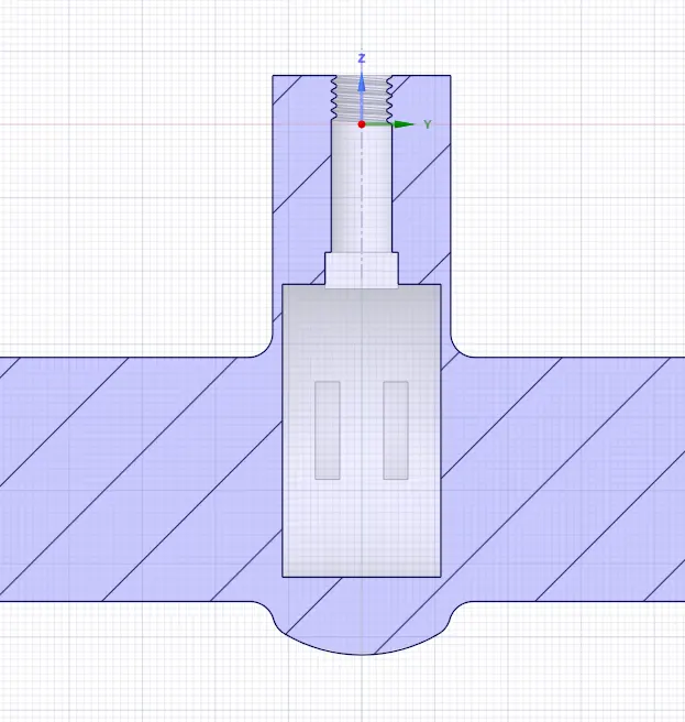
Residuals :
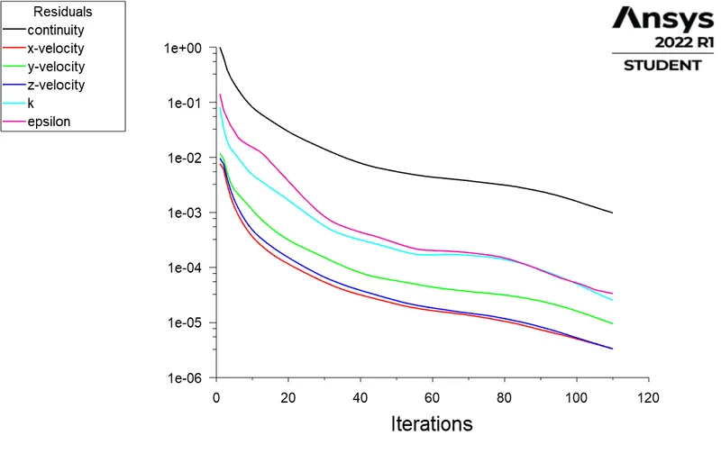
Mass flow rate :
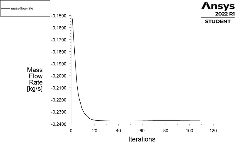
Velocity contour :
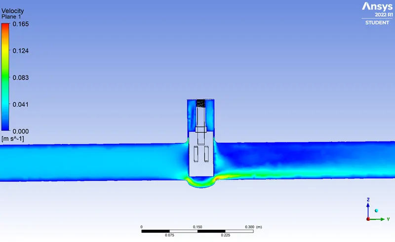
Case 3 :
Gate disc lift :30mm (30%)
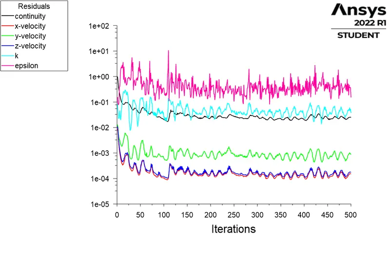
Residuals :
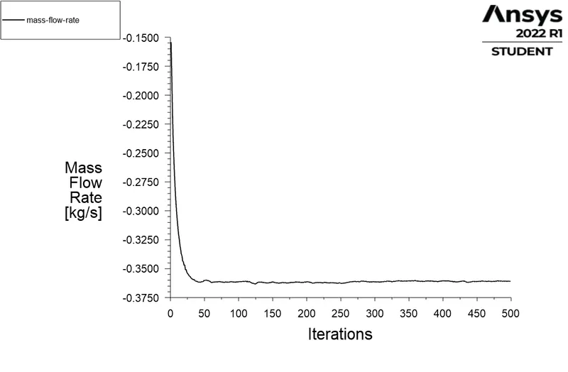
Mass flow rate :
Velocity contour :
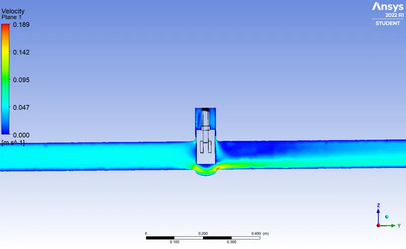
Case 4 :
Gate disc lift : 40mm (40%)
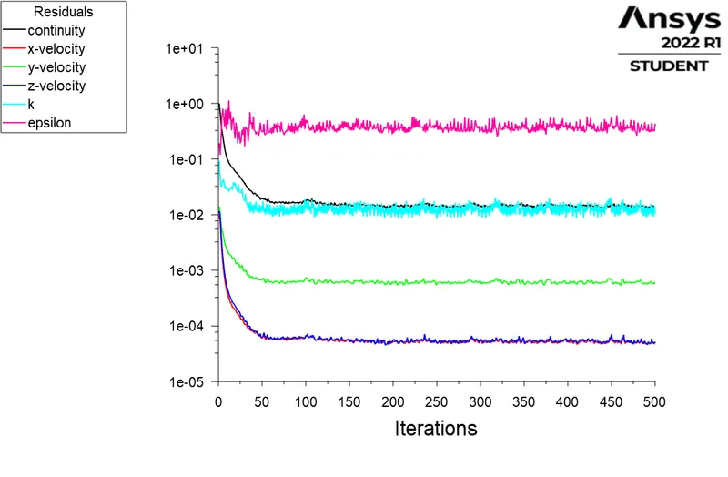
Residuals :
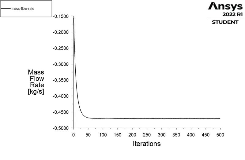
Mass flow rate :
Velocity Contour :
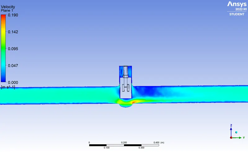
Case 5 :
Gate disc lift : 50mm (50%)
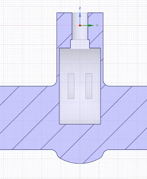
Residuals :
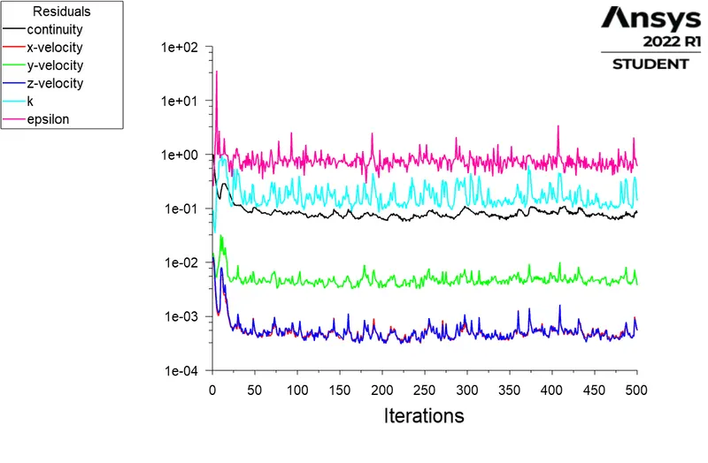
Mass flow rate :
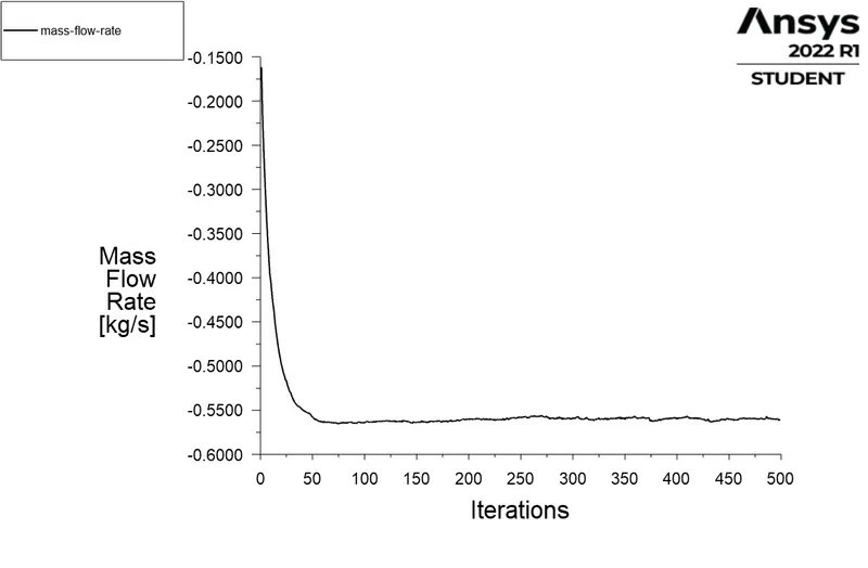
Velocity Contour:
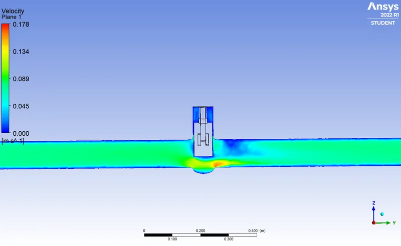
Case 6 :
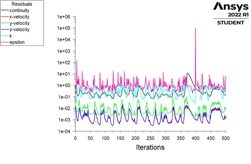
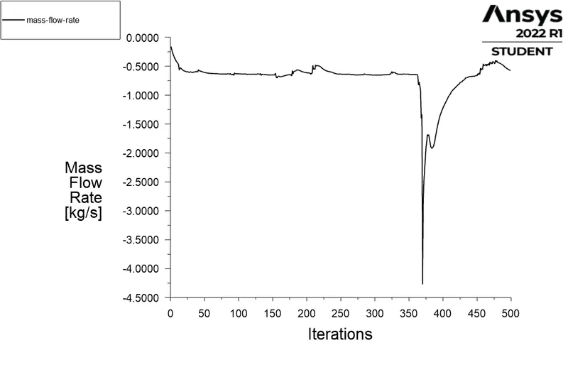
Gate disc lift : 60mm (60%)
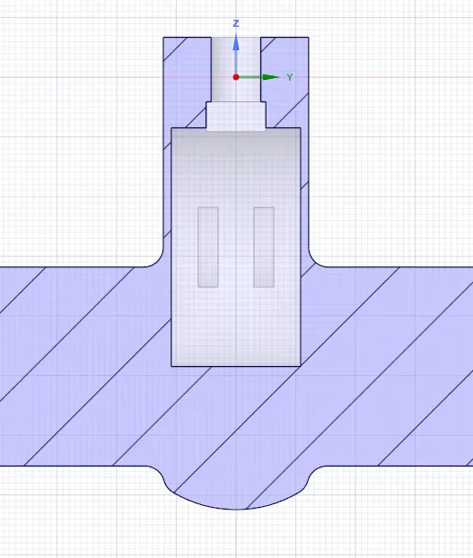
Residuals :
Mass flow rate :
Velocity Contour :
Case 7 :
Gate disc lift : 70mm (70%)
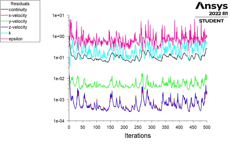
Residuals :
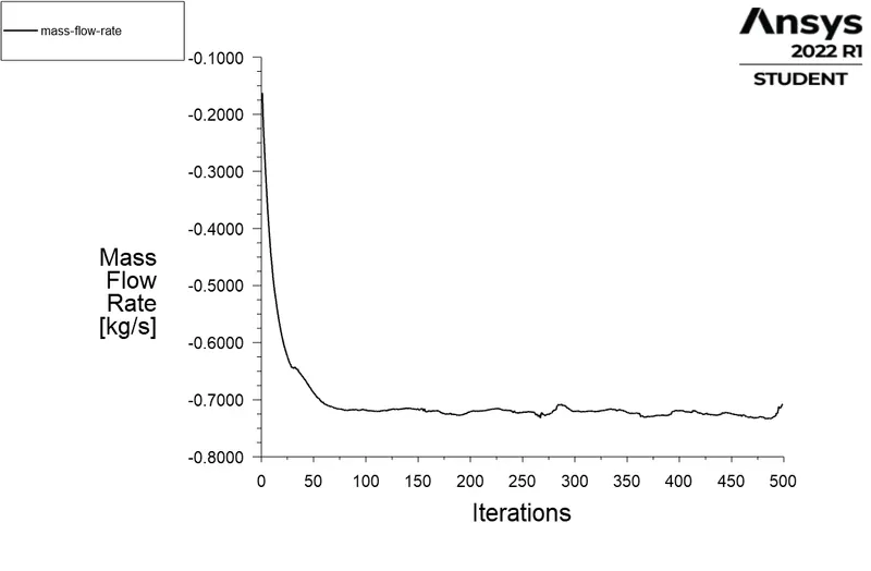
Mass flow rate :
Velocity Contour :
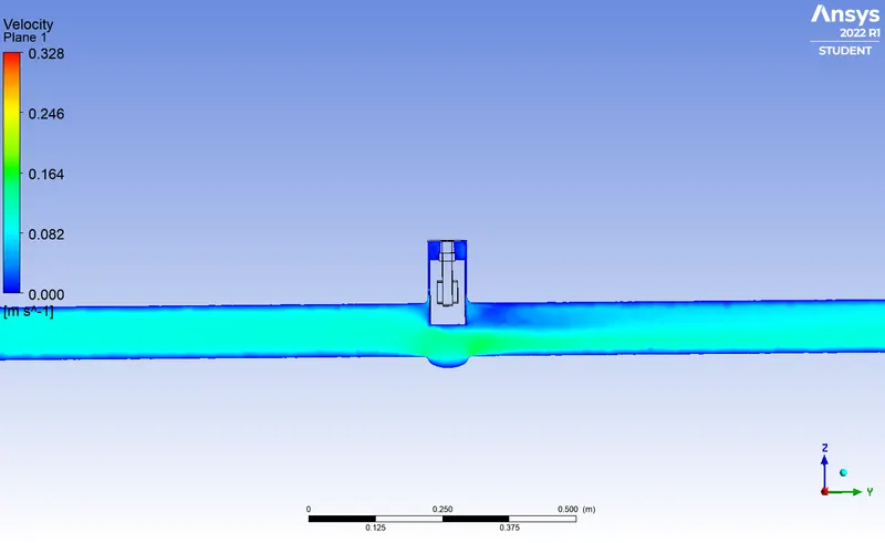
Case 8 :
Gate disc lift : 80mm (80%)
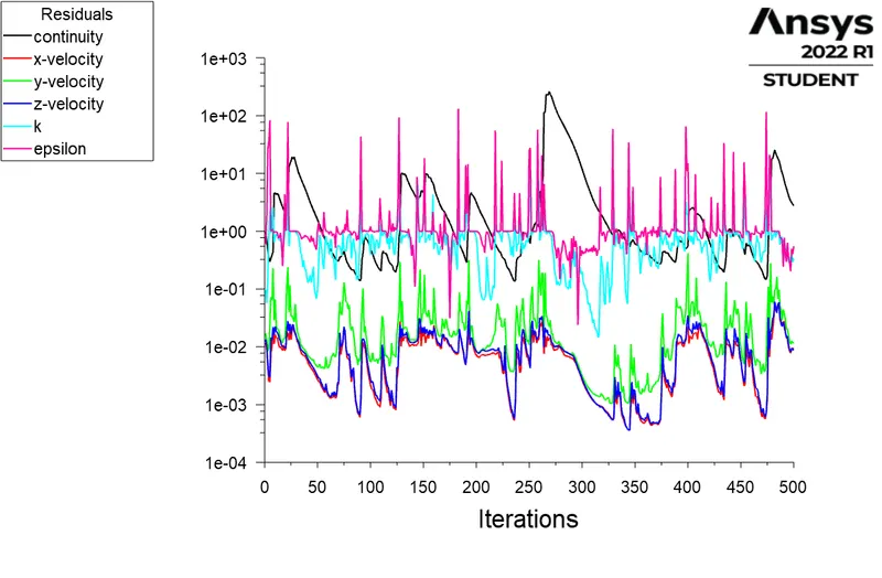
Residuals :
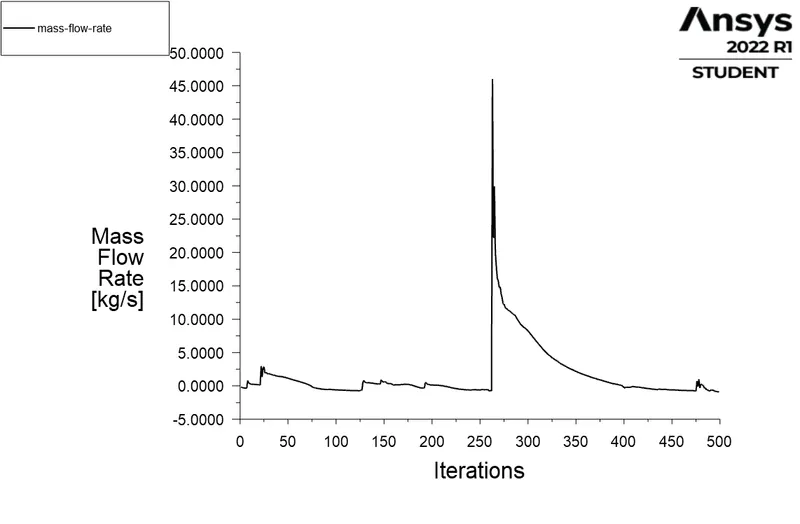
Mass flow rate :
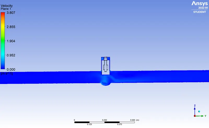
Velocity Contour :
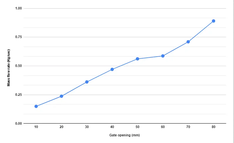
Mass Flow Rate vs Gate opening :
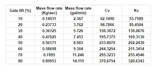
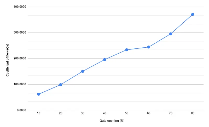
Gate lift (%) and Coefficient of flow (Cv) :
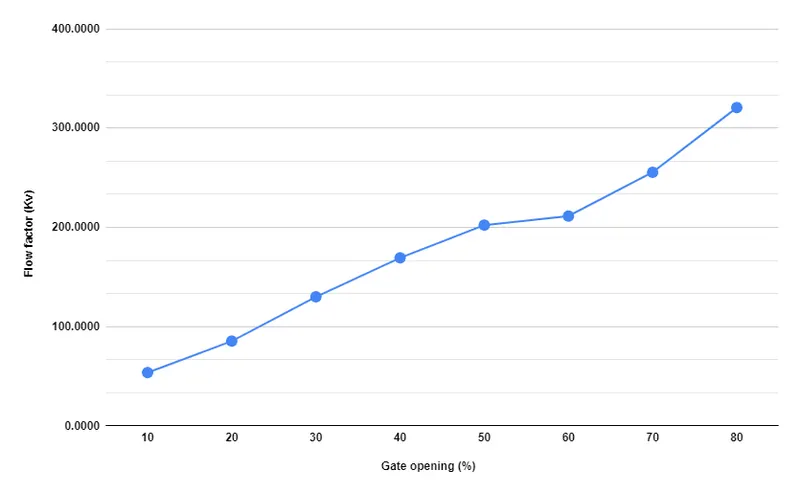
Gate lift (%) and Flow Factor (Kv) :
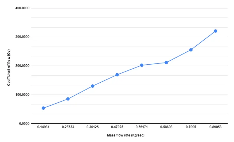
Mass Flow Rate and Coefficient of flow (Cv) :
Conclusion :
Cases 10% to 80% lift of Gate Disc valve was simulated successfully and the results were plotted
From the results it can be seen that :
- Mass flow rate increases with increase in gate opening
- Since all parameters are directly dependent on the flow rate they also increases.