Week -2
Aim :
- To make a Simulink model of Doorbell using solenoid block.
- To make a Simulink model of thermistor to sense the temperature of a heater & turn on or turn off the fan.
Objective 1 : To make a Simulink model of Doorbell using solenoid block.
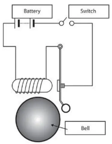
- In the above arrangement, when the switch is closed the electromagnet receives electrical power from the battery and pulls the metal arm to hit the bell producing sound.
- Create a situation where the switch is closed for 2 seconds and then released. Observe the physical movement of the plunger.
Block diagram :
Procedure :
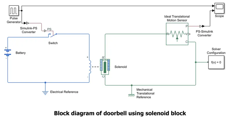
- Create a pulse generator, simulink to Physical signal converter,switch, battery and add an electrical reference to this circuit.
- Create a solenoid,ideal transnational motion sensor, mechanical transnational reference and solver configuration as a second circuit.
- Connect these circuits in two different circuits as shown in the below block diagram.
- Create an output for the system as scope by changing the Physical converter to simulink signal.
Result:
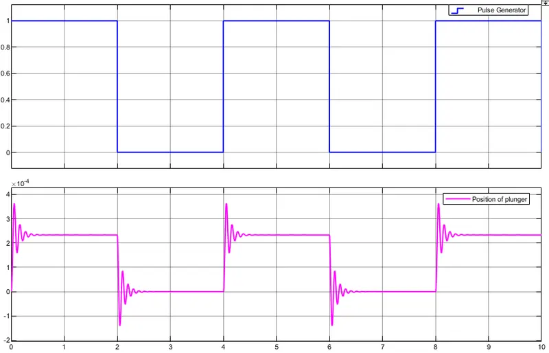
- The physical movement of the plunger in doorbell is shown by the ideal transnational motion sensor and time period is taken for 10seconds.
Conclusion :
- Simulink model of Doorbell using solenoid block is created and physical conditions are observed.
Objective 2 : To make a Simulink model of thermistor to sense the temperature of a heater & turn on or turn off the fan.
Theory:
In order to create a thermistor which senses the temperature of any object an controlled temperature source is required to sense the temperature. This observes the temperature and a cooling system is arranged to decrease the temperature by means of a radiator fan(a DC motor),etc to cool the system.
Use a thermistor to sense the temperature of a heater & turn on or turn off the fan as per below conditions:
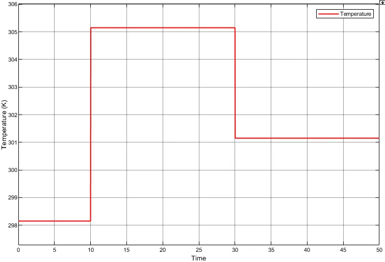
- Temperature source: 20 °C from 0 to 10 seconds, 27 °C from 10 to 30 seconds, 23 °C from 30 to 50 seconds
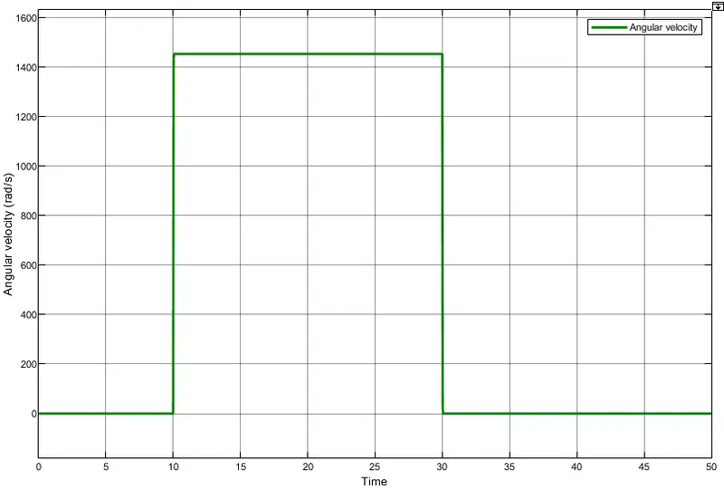
- Fan conditions: ON if the temperature above 25 °C, OFF otherwise
Block diagram:
Procedure :
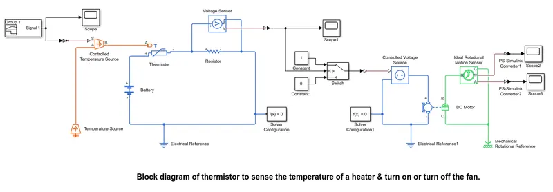
- Create a signal builder and convert the signal to physical signal to a controlled temperature source in the primary circuit.
- Use a thermistor which is connected to a voltage sensor and resistor by an electrical reference and solver configurations as a second circuit.
- Use a switch configuration whose threshold frequency limit by the given output of the second circuit and add constants to switch as 1 and 0 which makes the third circuit.
- The output of third circuit is connected to the controlled voltage source by an electrical reference which is linked to DC MOTOR.
- To sense the angular velocity and rotational motion of DC motor an ideal rotational motion sensor is created by the mechanical rotational reference and a slover configurator.
- For output of angular velocity and angular displacement of DC motor add scopes for output of ideal rotational motion sensor.
- Connect the circuits as shown in the below block diagram.
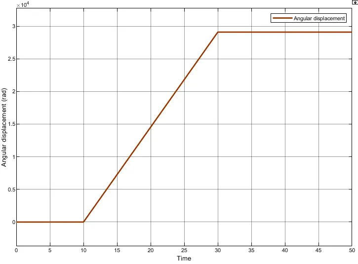
- Scope 2 shows the angular velocity of DC motor and scope 3 shows the angular displacement of dc motor.
Results :
- Input temperature
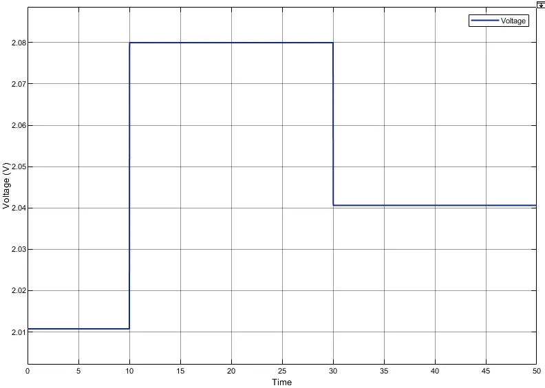
- Time vs Voltage
- Time vs Angular velocity of DC motor
- Time vs Angular displacement of DC motor
Conclusion :
- Simulink model of thermistor to sense the temperature of a heater & turn on or turn off the fan is created and physical conditions are observed.