Week - 4
AIM :
- To implement control logic of a “washing machine” using Stateflow.
- To make a Simulink chart for the “Gear shift” logic.
STUDY 1 :
To implement control logic of a “washing machine” using Stateflow.
Given Sequence :
- If the power supply is available, the system gets activated
- If the Water supply is not available, stop the process & indicate through LED
- Soaking time should be 200s followed by Washing time of 100s.
- Then rinsing happens for next 20s & dryer runs for 50s
After all the processes have completed turn on the finished LED
BLOCK DIAGRAM :
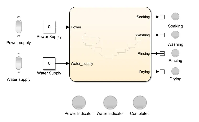
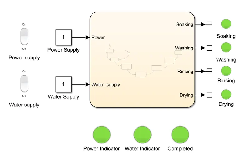
- Model of Washing machine
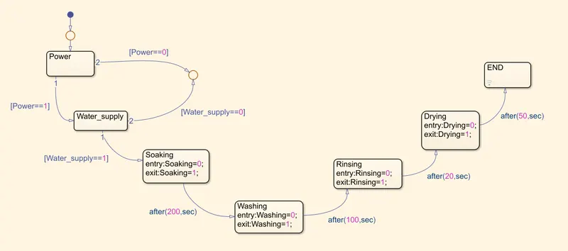
- Stateflow chart
EXPLANATION :
- For making the model we have to create a Stateflow chart with power, water, soak time, washing time, Rinsing, Drying and end of the cycle.
- To start with the charts we require a breakpoint added with chart Power (we can name the chart with any name to define the chart for our reference).
- From power to water we make a loop with conditions if power is one the flow of current goes to engage the water and when the water has one condition the washing machine cycle runs from soaking till the end.
- Here given soak time entry 0 and exit 1 with this we set breakpoint flow of water is for 200 seconds and once it reaches above 200 seconds it will go to next process washing. the washing, rinsing and dry are set as per the given time.
- Here input end=1 so the lamp will indicate when the display is one.
- After creating the charts we have to check the input and output through the symbols tool which is visible on the left side of the chart page. In the type column, we have to define the input and output.
- After giving the input and out we will be connecting the power and water to two constant and all the five outputs to display.
- Here connected inputs power and water to switch and lamps, all four cycles are then connected to display and lamps to indicate the washing cycle.
RESULTS :
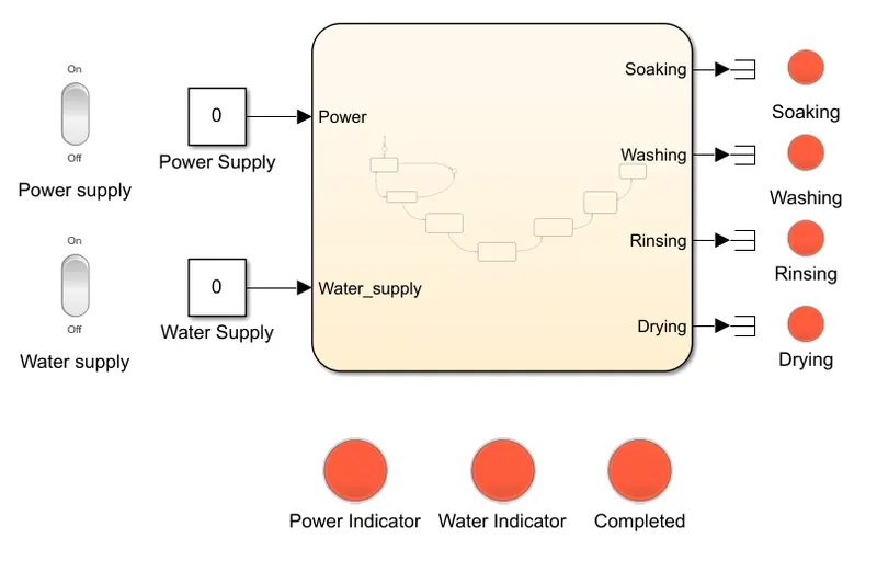
- Power OFF and water supply OFF
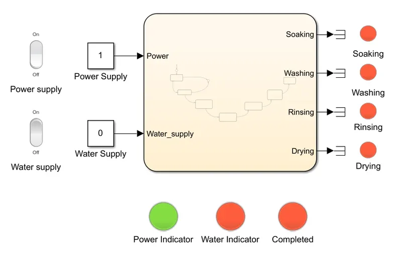
- Power ON and water supply OFF
- Power ON, water supply ON, all processes completed
CONCLUSION :
Control logic of a “washing machine” is successfully implemented using Stateflow.
MODEL LINK :
https://drive.google.com/file/d/1hFi5slJ2K-Bc2j6GhxbBArZFOXTWCEon/view?usp=sharing
STUDY 2 :
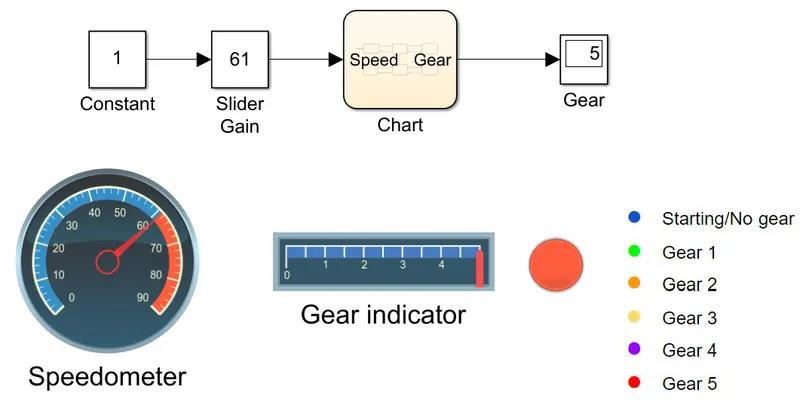
To make a Simulink chart for the “Gear shift” logic.
Given Condition :
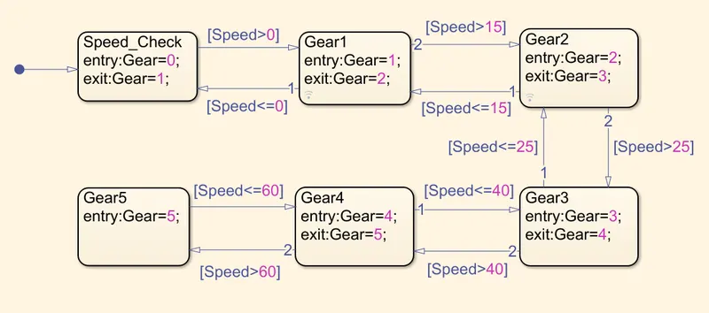
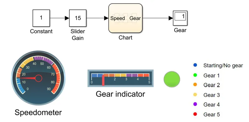
Speed Range(kmph) Gear
0 to 15 1
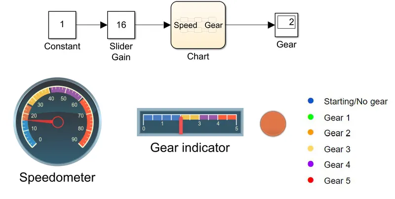
16 to 25 2
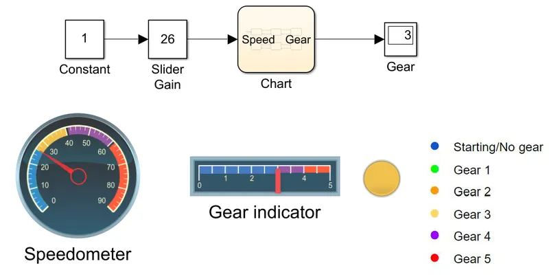
26 to 40 3
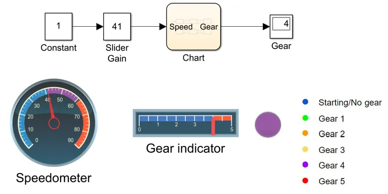
41 to 60 4
Above 61 5
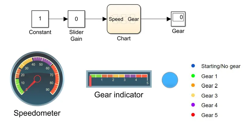
Give speed input while the simulation is running & display the gear number.
BLOCK DIAGRAM :
- Stateflow chart
PROCEDURE :
- Create a chart in simulink that consists of 8 blocks which denoted as Power,water,soaking,washing,Rinse,Dryer,Finish and no water supply.
- Apply the syntax for the given blocks as per the given conditions above.
- Add an input source for two blocks such as water and power supply.
- Add switches from the simulink library which creates the value as 0 for OFF and 1 as ON condition.
- Set the outputs for the parameter blocks in order to glow a bulb or an LED when the current process takes place.
RESULTS :
- No Gear State
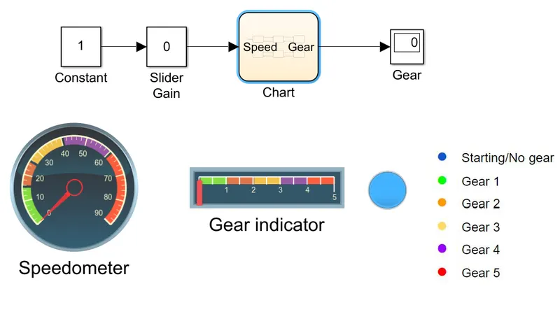
- Gear 1
- Gear 2
- Gear 3
- Gear 4
- Gear 5
CONCLUSION :
Simulink chart for the “Gear shift” logic is created by giving speed input while the simulation is running & the gear number is displayed.
MODEL LINK :
https://drive.google.com/file/d/1ayqkeEcx_ufoObz2ShcbSFPbBs2g4Lek/view?usp=sharing