Week 9 - Parametric study on Gate valve.
Objective: to perform a parametric study on the gate valve simulation by setting the opening from 10 to 80%.
- Obtain the mass flow rates at the outlet for each design point.
- Calculate the flow coefficient and flow factor for each opening and plot the graph.
- Discuss the result of the mass flow rate and flow coefficient.
Introduction
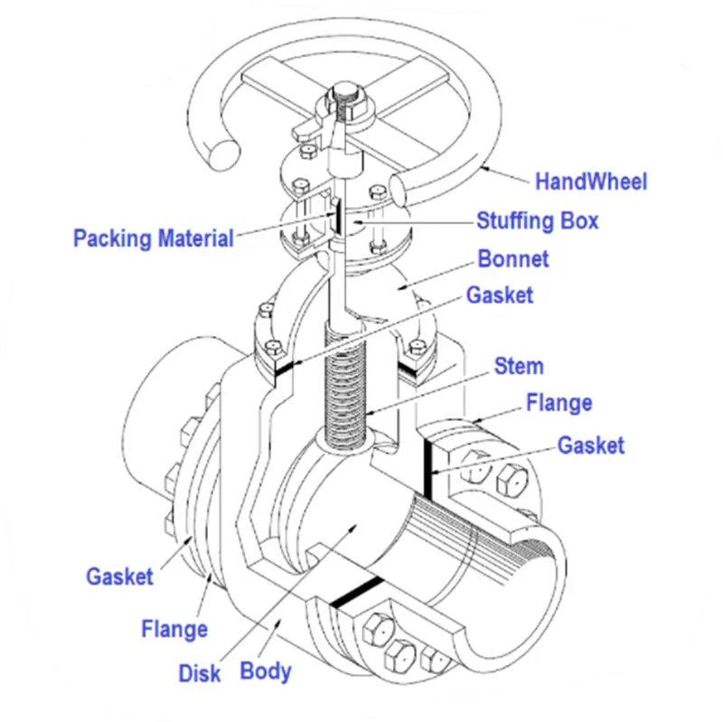
A gate valve, also known as sluice valve is a valve that opens by lifting a barrier(gate) out of the path of the fluid. gate valves require very little space along the pipe axis and hardly restrict the flow of fluid when the gate is fully opened. the gate faces can be parallel but are most commonly wedge-shaped (in order to be able to apply pressure on the ceiling surface).
Parametric study
One of the best ways to get value out of your simulation is to do parametric analysis. With very little marginal work a completed model can be parametrized to simulate scenarios limited only by your computational time and resources.
As you move forward in your design, you can access the impact that changing certain parameters can have on the design. The parameters can include dimensional parameters parametric study allows you to nominate parameters for evaluation, define the parameter range, specify the design constraints and analyze the results of each parameter variation.
Case setup
- Geometry
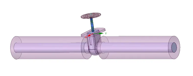
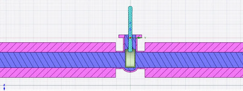
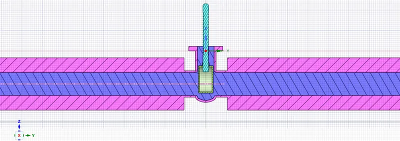
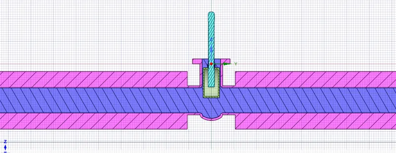
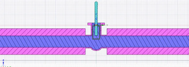
- Import geometry In SpaceClaim.
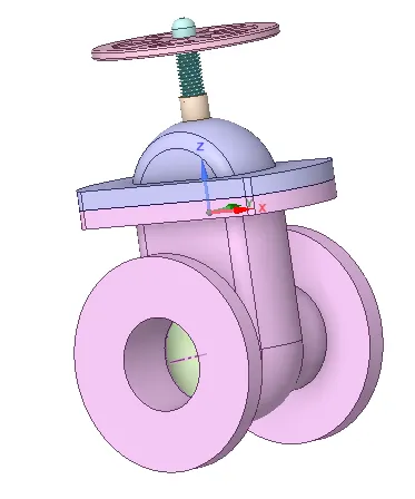
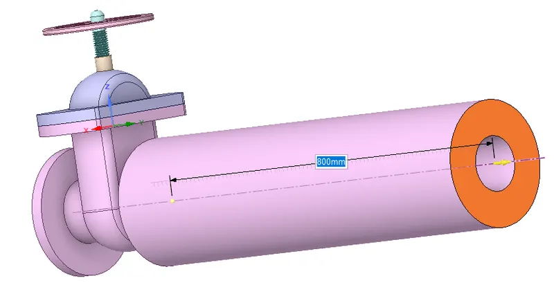
- Pull pipe to 800mm in both the sides.
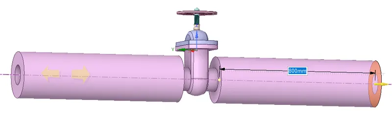
- Extract fluid volume.
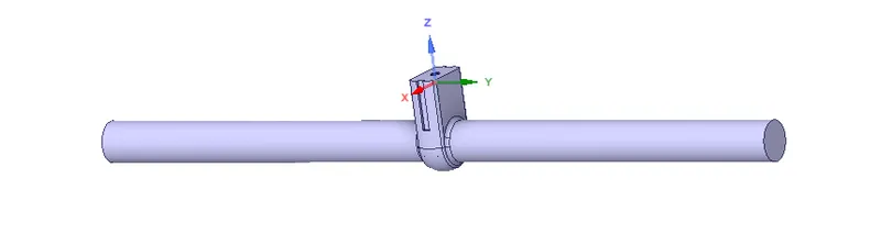
- Update volume body in context.
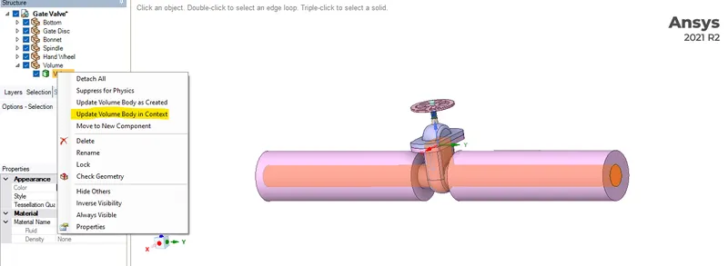
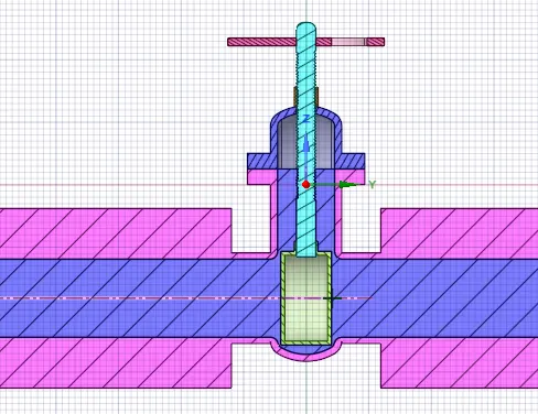
- Import geometry In SpaceClaim.
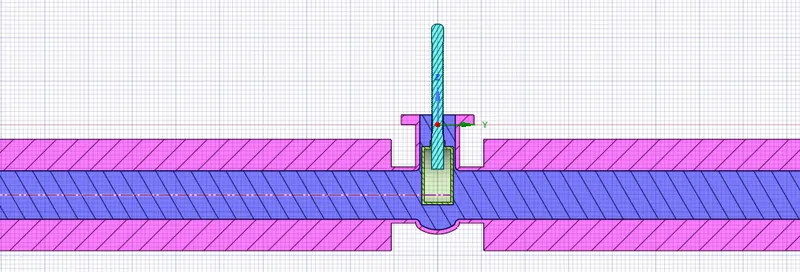
- Create parameterization group.
- Hide all components except 'spindle and gate disc'.
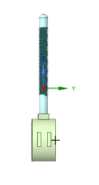
- select move tool from design.
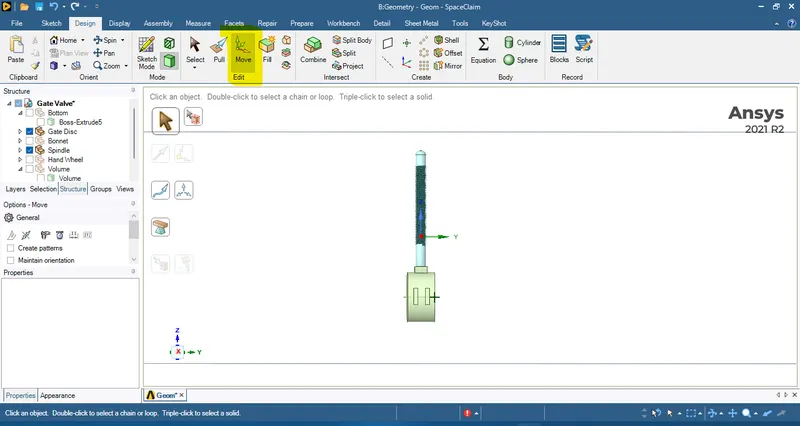
- now select body selection.
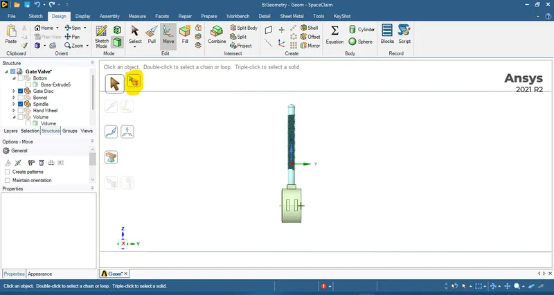
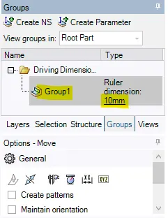
- drag the gate disc a little bit in z-direction now enter any value e.g., 10mm.
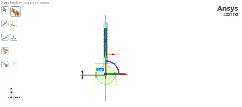
- Go to group and click on create parameter.
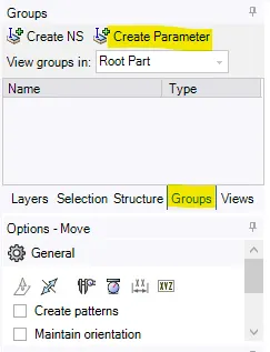
- Now parameter has been created. where we can change the dimension.
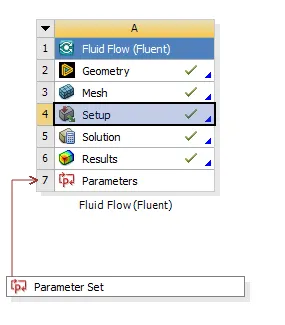
- Hide all components except 'spindle and gate disc'.
- Meshing
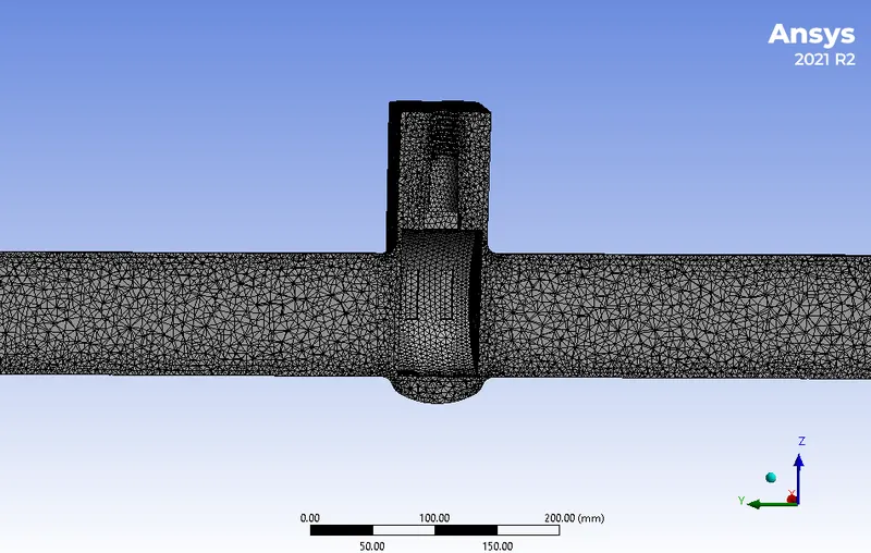
Mesh the fluid volume of gate valve.
baseline mesh
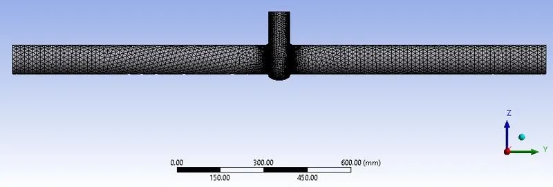
refined mesh(5mm)

- Setup
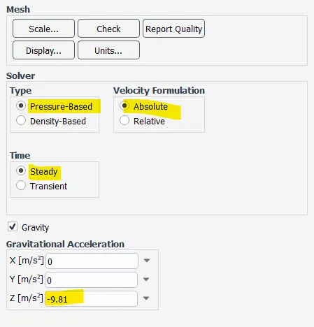
- general setup
- Analysis type: steady state
- solver: pressure based
- Velocity formulation: absolute
- gravity enabled with the value of -9.81`m/s^2` in z-direction.
- material selection
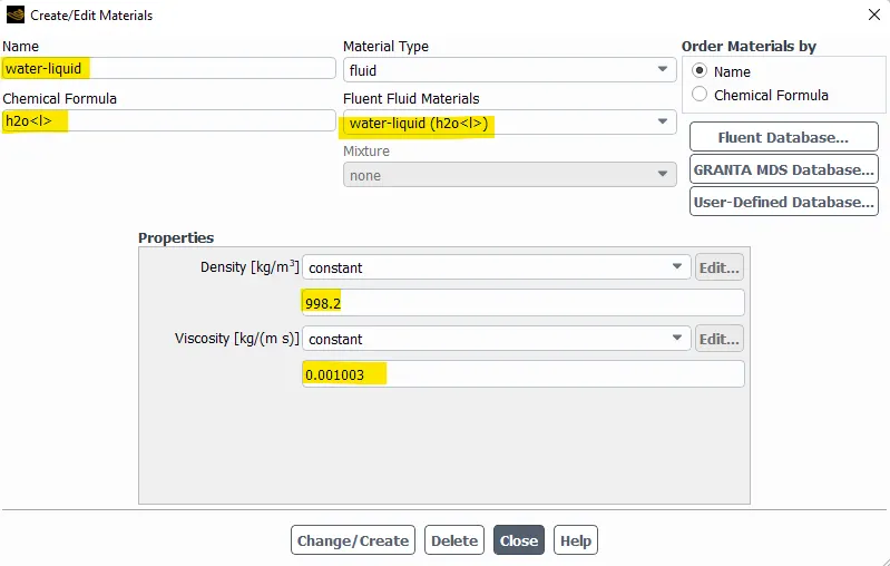
- material: water-liquid(`H_2O`)
- Density: 998.2`[Kg]/m^3`
- viscosity: 0.001003`[Kg]/[m*s]`
- viscous model
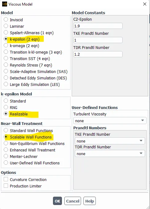
- Model: K-epsilon
- K-epsilon model: realizable
- near wall treatment: Scalable wall function
- Boundary condition
- inlet
- type: pressure inlet
- Guage total pressure: 10Pa
- outlet
- type: pressure outlet
- Guage total pressure: 0Pa
- wall
- type: wall
- wall motion: stationary wall
- shear condition: no slip
- inlet
- general setup
- Create Report definition for
- mass flow rate outlet
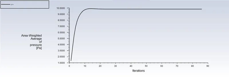
- pressure at inlet
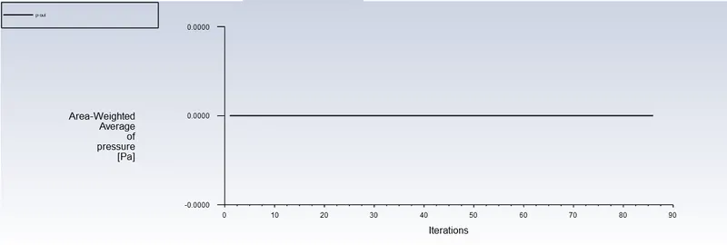
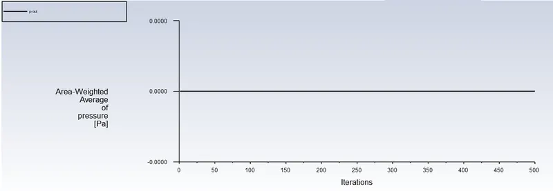
- pressure at outlet
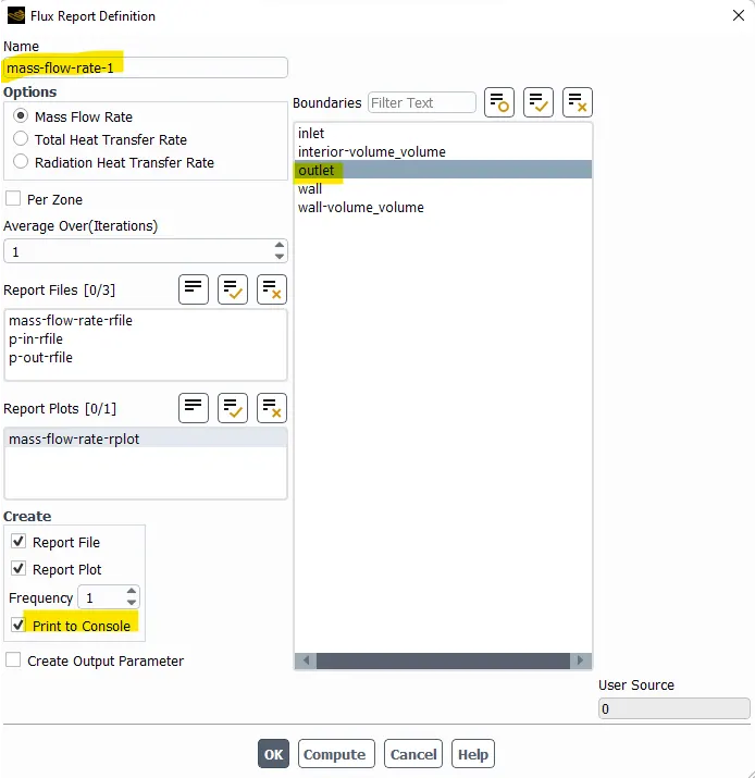
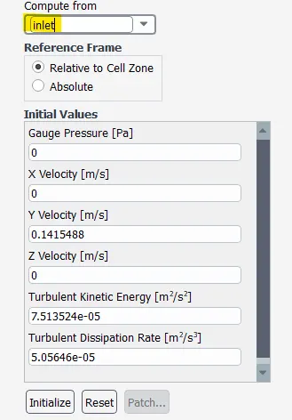
- Initialization: standard initialization from inlet
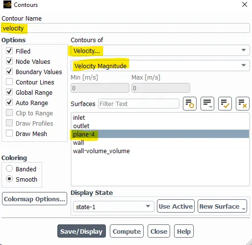
- Create velocity contour.
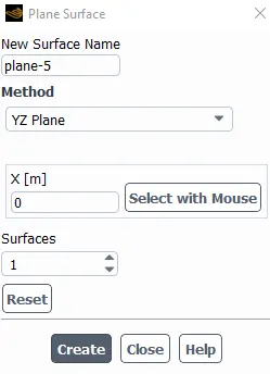
- insert a y-z plane.
- create a contour of velocity at plane.
- insert a y-z plane.
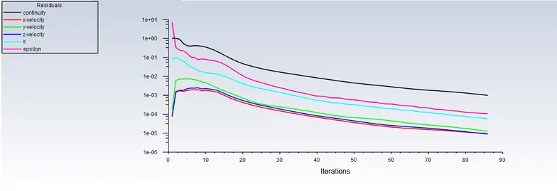
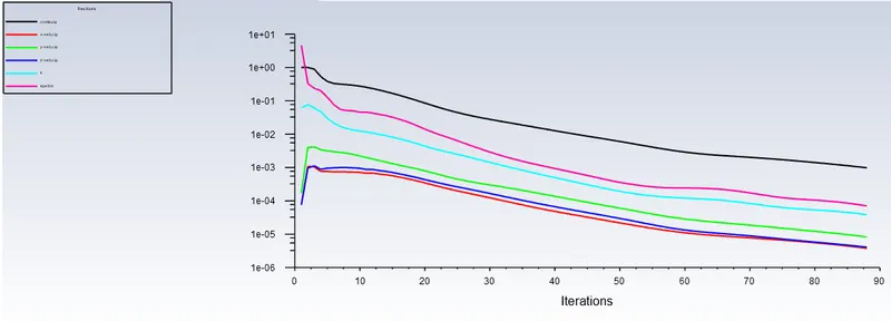
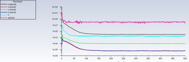
- Run simulation for 300 to 500 iterations.
Result
10mm opening

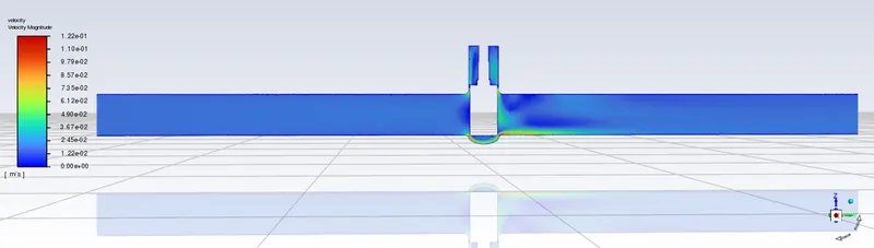
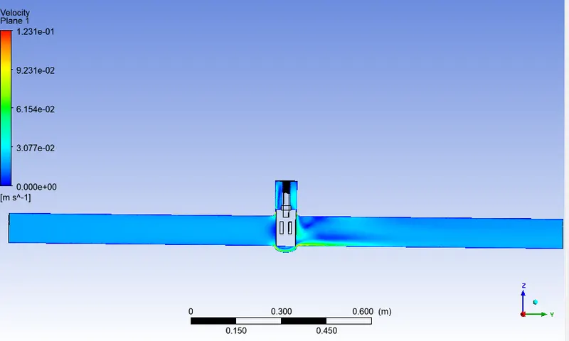
20mm opening
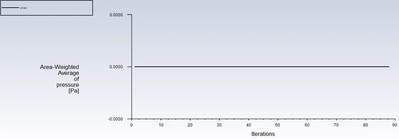
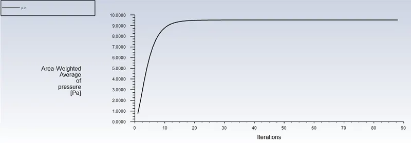
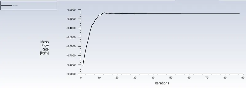
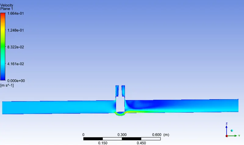
30mm opening
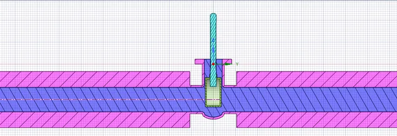
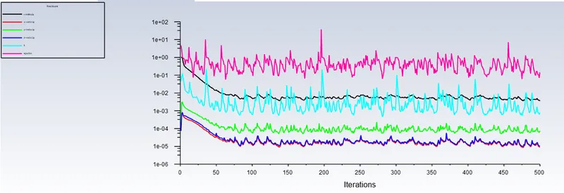
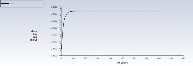
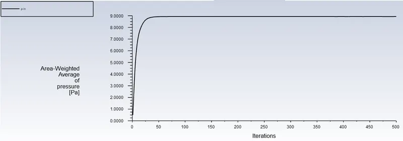
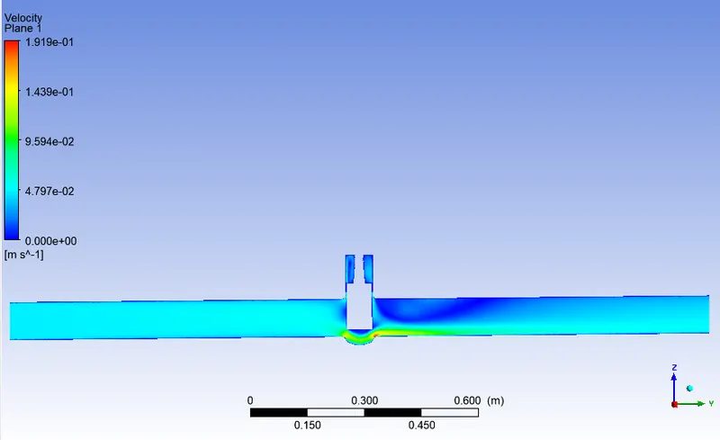
40mm opening
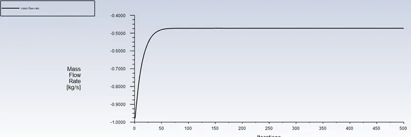
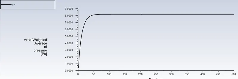
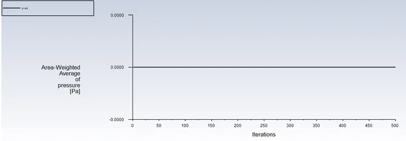
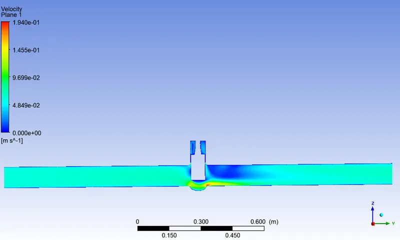
50mm opening
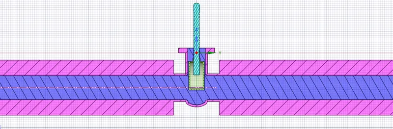
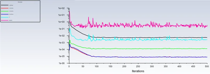
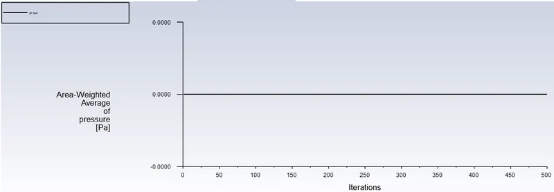
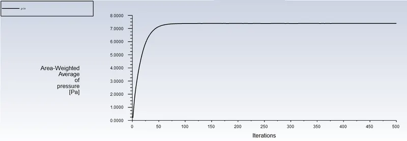
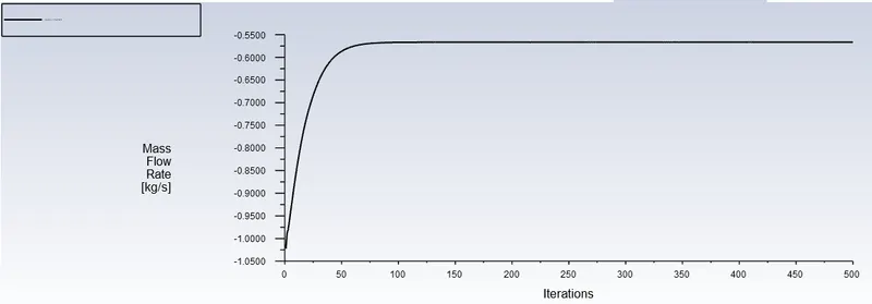
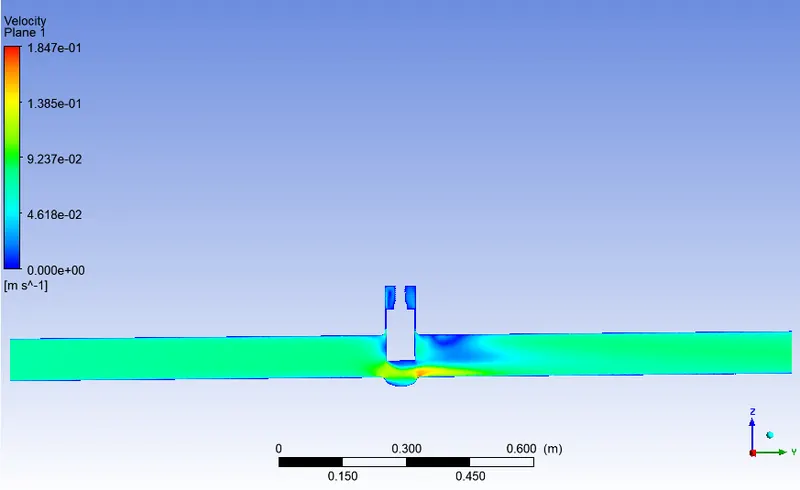
60mm opening
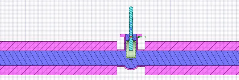
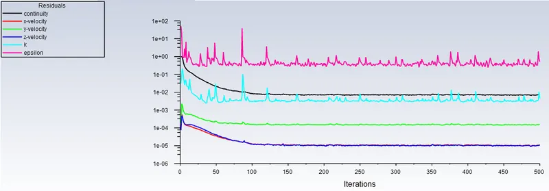
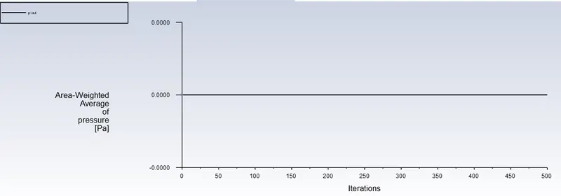
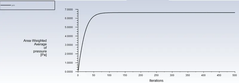
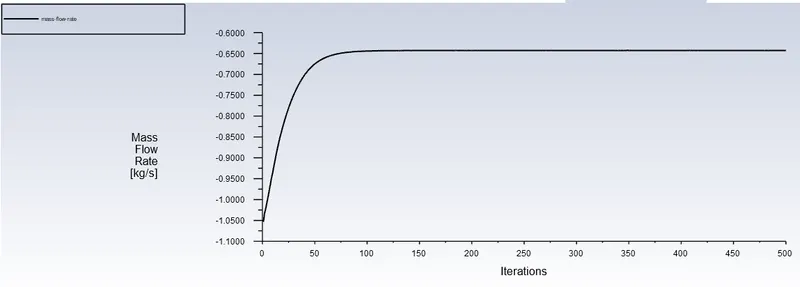
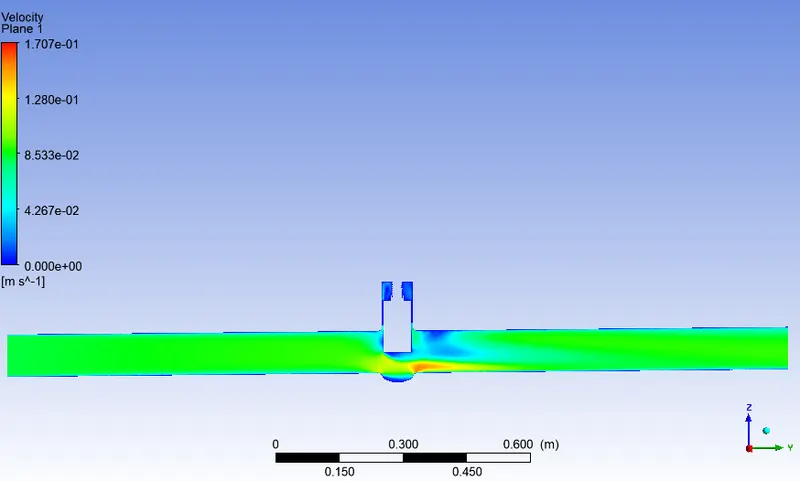
70mm opening.
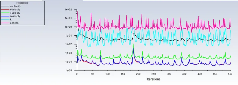
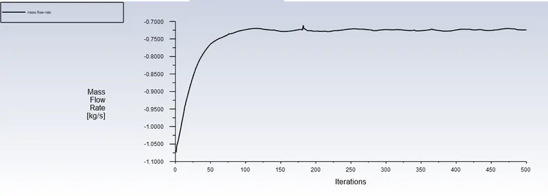
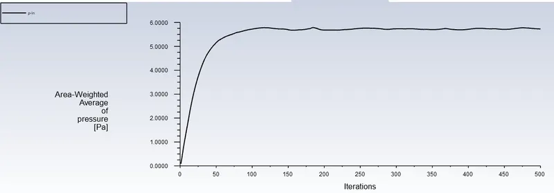
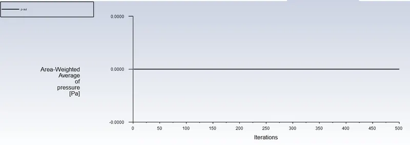
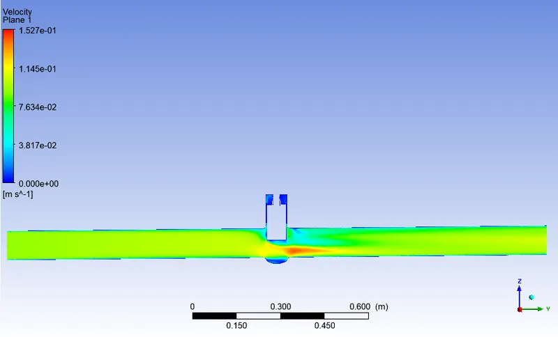
80mm opening
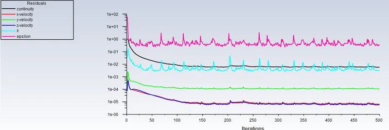
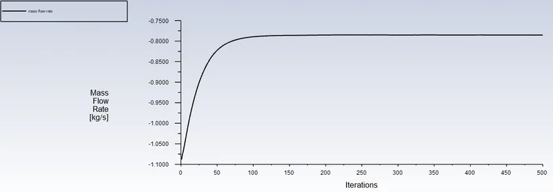
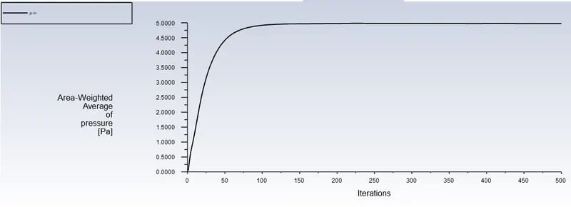
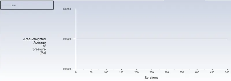
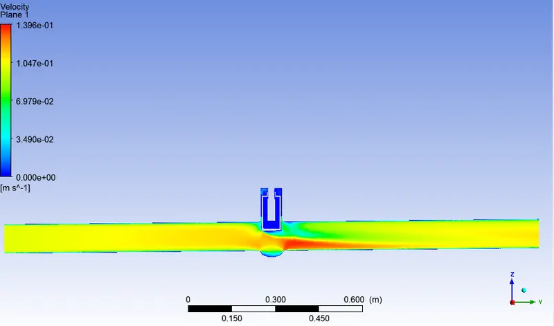
Flow coefficient `C_v`
the flow coefficient of a device is a relative measure of its efficiency at following fluid flow. it describes the relationship between the pressure drop across an orifice valve or other assembly and the corresponding flow rate.
Mathematically the flow coefficient `C_v` can be expressed as:
`C_v=Qsqrt([SG]/[DeltaP])`
where;
- Q is the flow rate(expressed in US gallons per minute).
- SG is the specific gravity of the fluid. (for water=1)
- `DeltaP` is the pressure drop across the valve (expressed in psi).
Flow factor `K_v`
the metric equivalent flow factor (`K_v`commonly used in Europe and Asia) is calculated using metric units.
`K_v=Qsqrt((SG)/(DeltaP))`
where;
- Q is the flow rate(expressed in cubic meters per hour).
- SG is the specific gravity of the fluid. (for water=1)
- `DeltaP` is the pressure drop across the valve (expressed in bar).
`K_v` can be calculated from `C_v` using the equation given below:
`K_v=0.865*C_v`
The `K_v` factor of a valve indicates the water flow in `m^3/[hr]`, at a pressure drop across the valve of `[1kgf]/[cm^2]` when the valve is completely open.
Observation table
|
Case |
Gate disc lift (mm) |
Mass flow rate (`[Kg]/s`) |
Flow coefficient |
Flow factor |
Inlet pressure (Pa) |
Outlet pressure (Pa) |
Pressure gradient (Pa) |
|
1 |
10 |
0.14845156 |
61.78 |
53.44 |
9.82 |
0 |
9.82 |
|
2 |
20 |
0.24043291 |
100.06 |
86.56 |
9.53 |
0 |
9.53 |
|
3 |
30 |
0.36239788 |
150.82 |
130.46 |
8.93 |
0 |
8.93 |
|
4 |
40 |
0.47278271 |
196.77 |
170.2 |
8.18 |
0 |
8.18 |
|
5 |
50 |
0.56675853 |
235.88 |
204.03 |
7.38 |
0 |
7.38 |
|
6 |
60 |
0.64287463 |
267.55 |
231.43 |
6.64 |
0 |
6.63 |
|
7 |
70 |
0.7243075 |
301.45 |
260.75 |
5.73 |
0 |
5.73 |
|
8 |
80 |
0.7854319 |
326.89 |
282.76 |
4.98 |
0 |
4.98 |
Plots
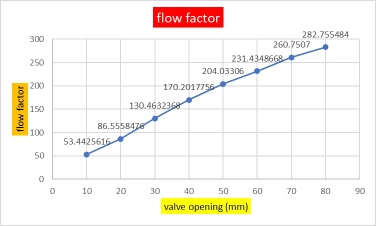
valve opening vs flow factor
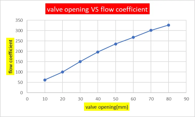
valve opening vs flow coefficient
Conclusion
- mass flow rate gradually increases as the lift of the gate disc is increased.
- parametric study is time reducing option when studying the effect of change of certain parameters on system.
- flow coefficient and flow factor gradually increase as the valve opening increases.