Week 9 - Parametric study on Gate valve.
Aim: To perform a parametric study on the gate valve by setting the opening from 10% to 80%.
Introduction & Theory- A gate valve, also known as a sluice valve, is a valve that opens by lifting a barrier (gate) out of the path of the fluid. Gate valves require very little space along the pipe axis and hardly restrict the flow of fluid when the gate is fully opened. The gate faces can be parallel but are most commonly wedge-shaped (in order to be able to apply pressure on the sealing surface).
Gate valves are used to shut off the flow of liquids rather than for flow regulation. When fully open, the typical gate valve has no obstruction in the flow path, resulting in very low flow resistance.
Gate valves are mostly used with larger pipe diameters (from 2" to the largest pipelines) since they are less complex to construct than other types of valves in large sizes.
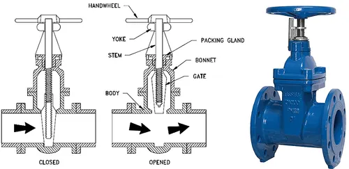
Parts of a gate valve:
Bonnet
Bonnets provide leakproof closure for the valve body. Gate valves may have a screw-in, union, or bolted bonnet. A screw-in bonnet is the simplest, offering a durable, pressure-tight seal. A union bonnet is suitable for applications requiring frequent inspection and cleaning. It also gives the body added strength. A bolted bonnet is used for larger valves and higher pressure applications.
Knife gate valve:
For plastic solids and high-viscosity slurries such as paper pulp, a specialty valve known as a knife gate valve is used to cut through the material to stop the flow. A knife gate valve is usually not wedge-shaped and has a tapered knife-like edge on its lower surface.In 1928, the Introduction of the first knife gate valve, the "Massaventil" (Pulp stock valve / MV), was engineered by Mr. Canell. In sweden, Stafsjö Valves AB.
Solving and Modelling approach:
The conventional modeling and solving method will be initially used which comprises Geometry, meshing, solver settings and then post-processing, the new approach here will be the application of parametric study, one of the dimensions that are the lift of the gate will be parameterized, so that when the new design points are created in the parametric tab the Spaceclaim, Mesher, and Fluent will automatically calculate the parametric output results which in this case is the mass flow rate at the output, so instead of performing a whole different simulation for every case we parametrise the setup in order to conserve time.
_ _ _ _ _ _ _ _ _ _ _ _ _ _ _ _ _ _ _ _ _ _ _ _ _ _ _ _ _ _ _ _ _ _ _ _ _ _ _ _ _ _ _ _ _ _ _ _ _ _ _ _ _ _ _ _ _ _ _ _ _ _ _ _ _ _ _ _ _ _ _ _ _ _ _ _
Pre-processing and solver settings:
Geometry:
The following .step file was imported into spaceclaim to prep it for further processes. 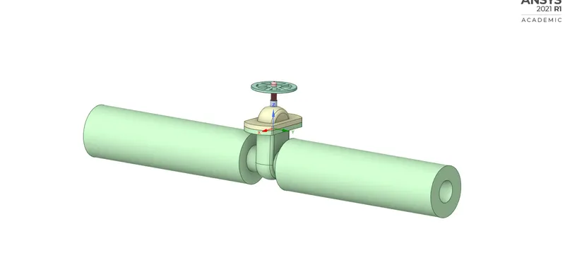
From the step file the fluid volume was extracted while creating a parametric function for the linear displacement of the gate disc, the following volume was extracted for 10mm movement of the gate disc. 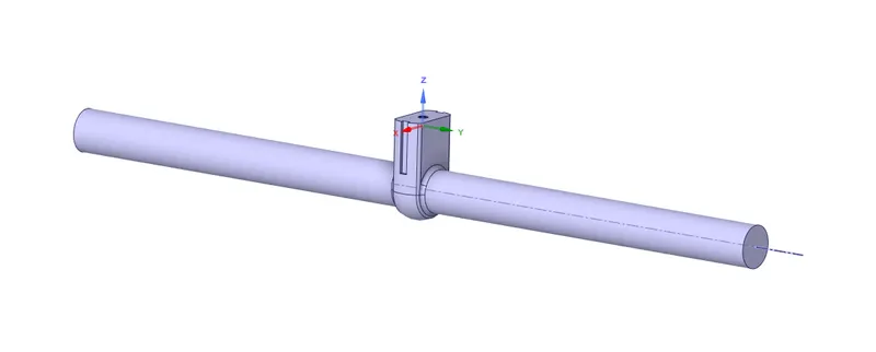
2) Meshing-
Element Size- 15 mm
Nodes- 31798
Elements- 149886
Details of Mesh- 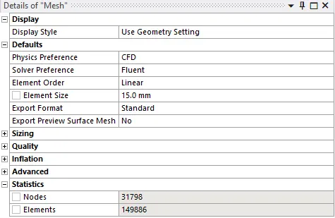
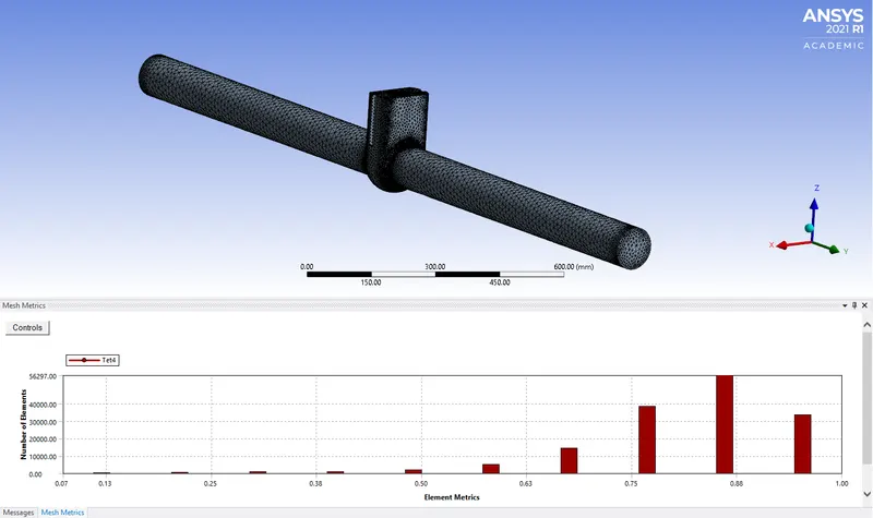
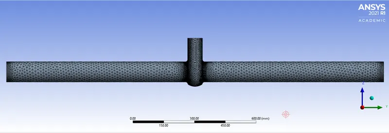
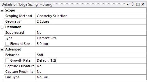
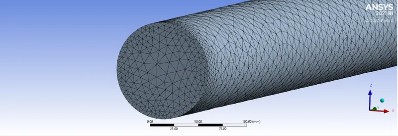
Edge sizing was done on both the inlet and outlet surfaces to capture the curvature better.
The following setting were applied for edge capture.
3) Setup-
General Settings- 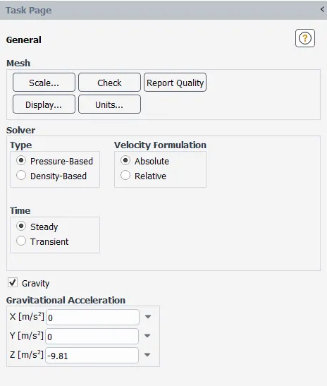
Viscous Model- 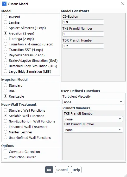
The k-epsilon was used since the flow is turbulent calculation for reynolds no. was done using the formula  and reynolds no. was significantly higher than 2000 so since the flow is turbulent K-epsilon model wasdeemed suitable.
Material Properties- 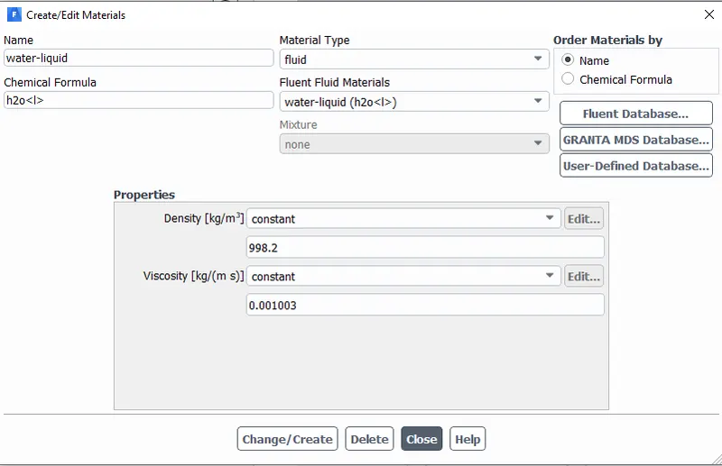
Report Creation-
A parametric definition was created for flux report for mass flow rate across the output surface.
Intialization-
Method- Standard
Calculation settings-
Time scale Factor- 1
No. of Iterations- 250
_ _ _ _ _ _ _ _ _ _ _ _ _ _ _ _ _ _ _ _ _ _ _ _ _ _ _ _ _ _ _ _ _ _ _ _ _ _ _ _ _ _ _ _ _ _ _ _ _ _ _ _ _ _ _ _ _ _ _ _ _ _ _ _ _ _ _ _ _ _ _ _ _ _ _ _
Results-
For 10 mm opening- 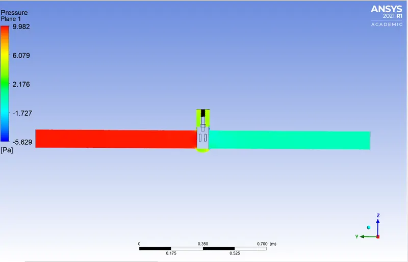
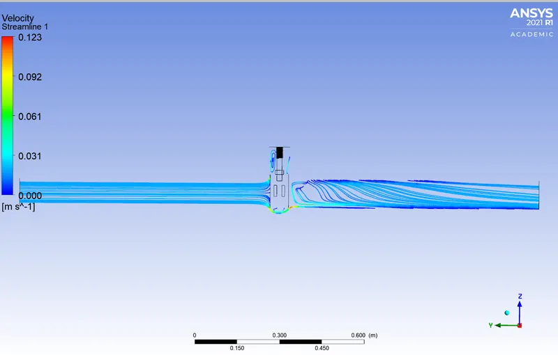
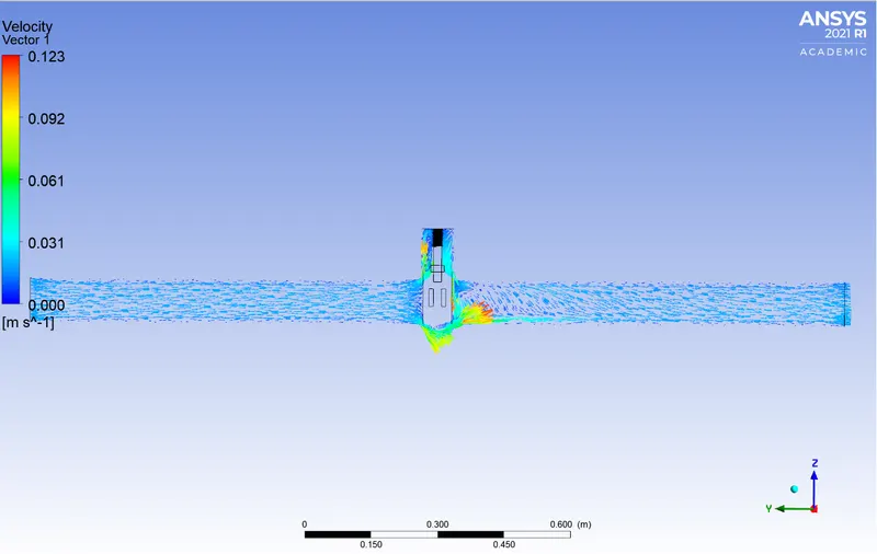
For 20 mm opening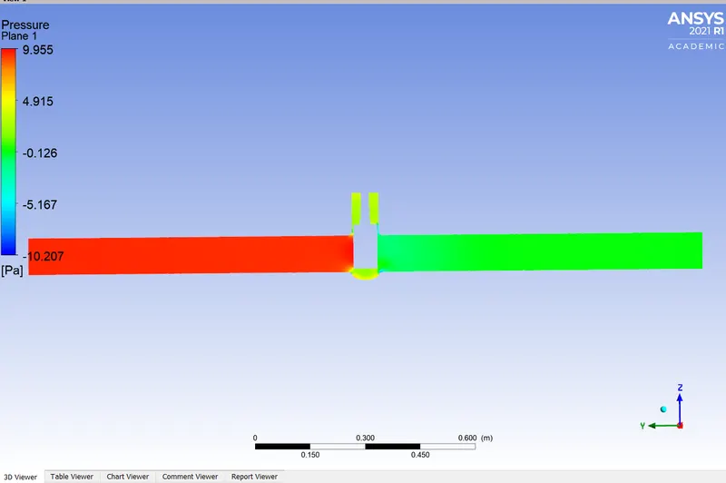
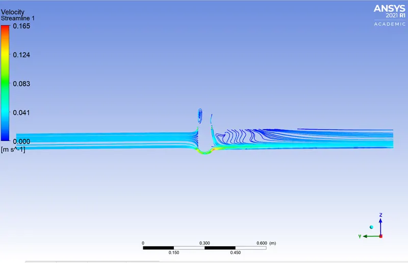
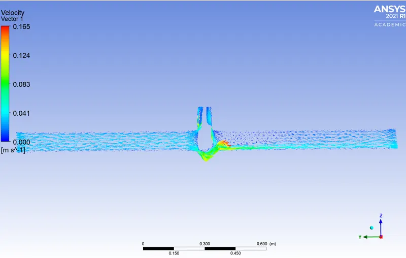
For 30mm opening-
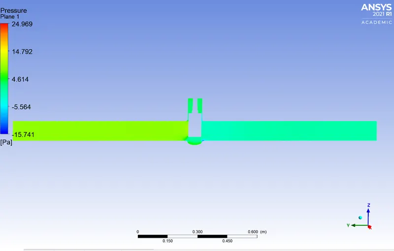
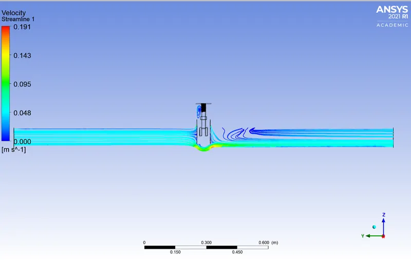
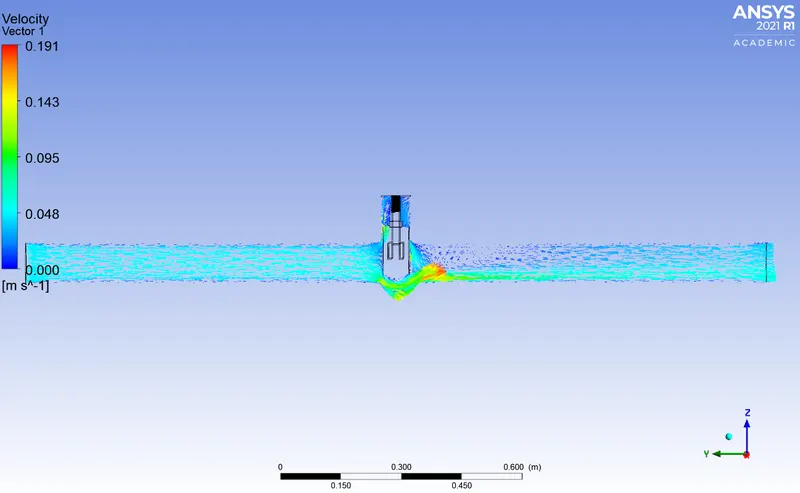
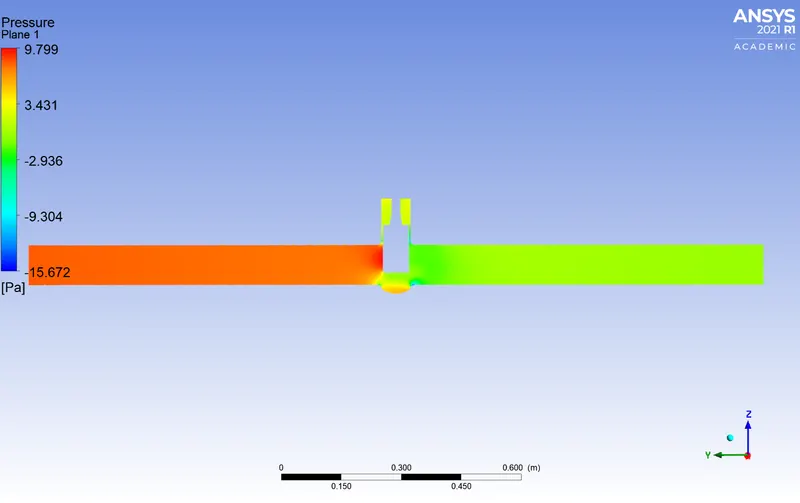
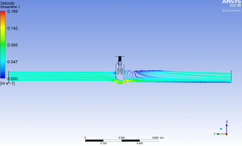
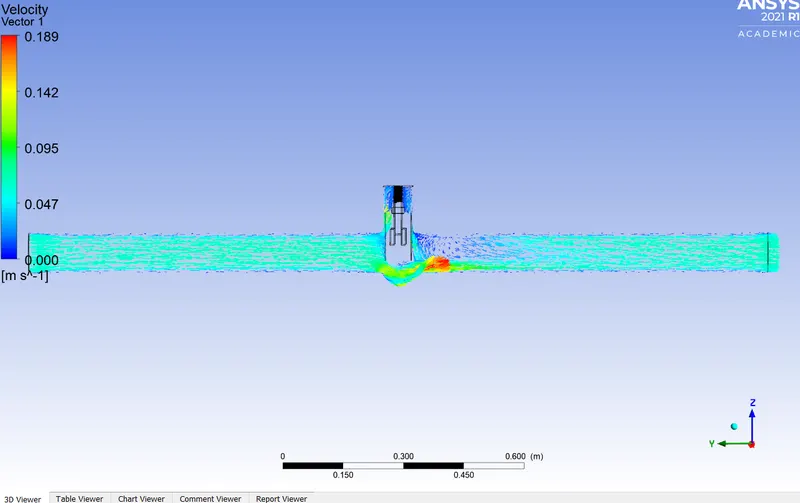
4) For 40mm Opening-
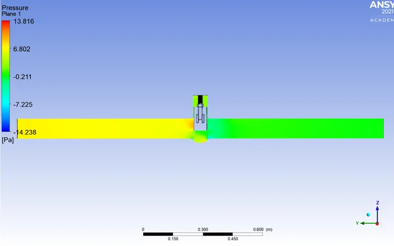
5) For 50mm opening-
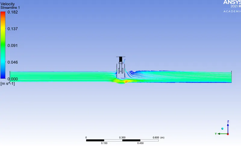
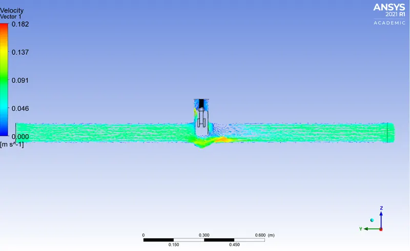
6) For 60mm opening-
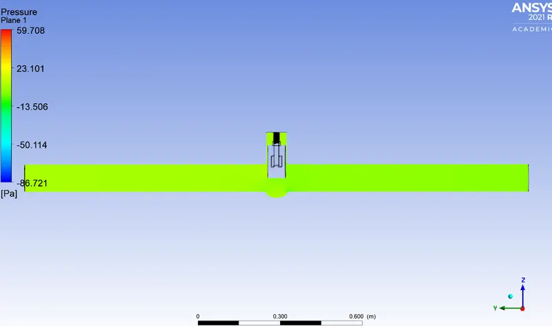
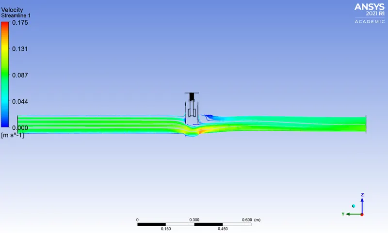
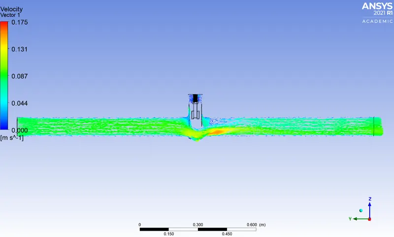
7) For 70mm opening-
8) For 80 mm opening-
_ _ _ _ _ _ _ _ _ _ _ _ _ _ _ _ _ _ _ _ _ _ _ _ _ _ _ _ _ _ _ _ _ _ _ _ _ _ _ _ _ _ _ _ _ _ _ _ _ _ _ _ _ _ _ _ _ _ _ _ _ _ _ _ _ _ _ _ _ _ _ _ _ _ _ _
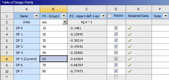
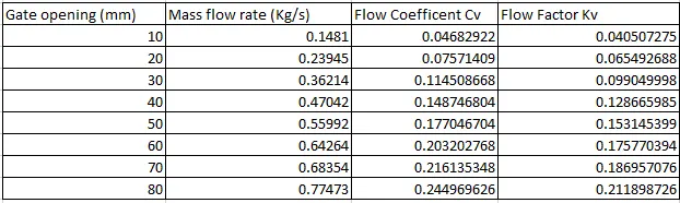
Mass flow rate values-
Flow Coeffiecient Cv-
The flow coefficient of a device is a relative measure of its efficiency at allowing fluid flow. It describes the relationship between the pressure drop across an orifice valve or other assembly and the corresponding flow rate.
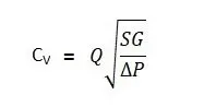
where:
- Q is the rate of flow (expressed in US gallons per minute),
- SG is the specific gravity of the fluid (for water = 1),
- ΔP is the pressure drop across the valve (expressed in psi).
In more practical terms, the flow coefficient Cv is the volume (in US gallons) of water at 60 °F that will flow per minute through a valve with a pressure drop of 1 psi across the valve.
Flow factor Kv-
The metric equivalent flow factor (Kv; commonly used everywhere else in the world with the exception of the United States) is calculated using metric units :

where
- Kv is the flow factor (expressed in
 ).
). - Q is the flowrate (expressed in cubic metres per hour
 ]),
]), - SG is the specific gravity of the fluid (for water = 1),
- ∆P is the differential pressure across the device (expressed in [bar]).
Kv can be calculated from Cv using the equation:

Calculation of Kv and Cv.
For case 1-
Lift value=10
Q= 0.1481
SG= 1
 = 10
= 10
Cv= `0.1481sqrt(1/10)`
Cv= 0.04680
Kv= 0.865.Cv
Kv= 0.865*0.04680
Kv= 0.04048
Similarly the Calculation for the rest of the cases are done and the solution is provided below.
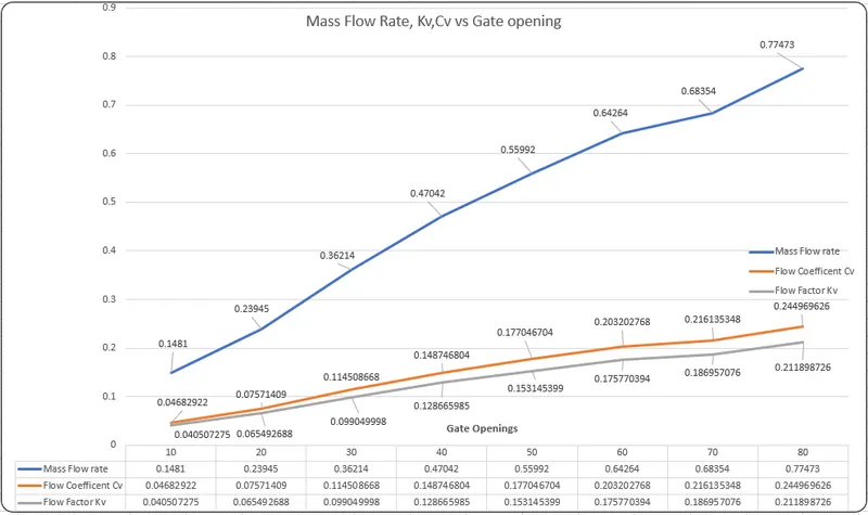
Graph
_ _ _ _ _ _ _ _ _ _ _ _ _ _ _ _ _ _ _ _ _ _ _ _ _ _ _ _ _ _ _ _ _ _ _ _ _ _ _ _ _ _ _ _ _ _ _ _ _ _ _ _ _ _ _ _ _ _ _ _ _ _ _ _ _ _ _ _ _ _ _ _ _ _ _ _
Conclution-
1) It is clearly evident that mass flowrate increases as the gate opening value increases since there is an increase in the cross-sectional area of the region more water can flow at a given time.
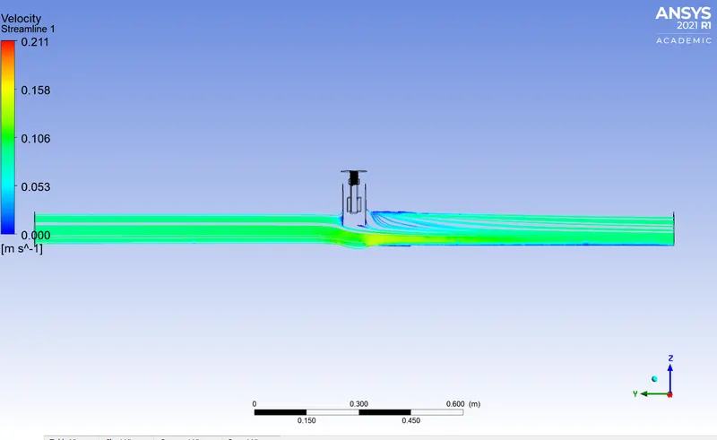
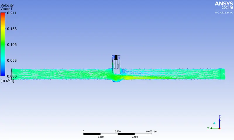
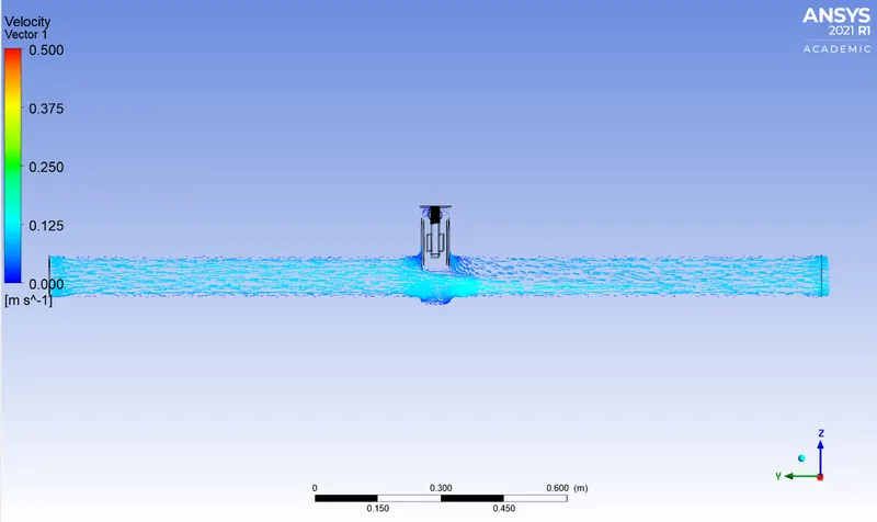
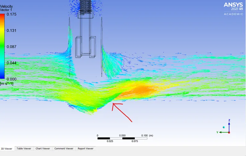
2) From the velocity vectors the velocity in the first case is the lowest and it keeps on increases as the gate disc rises.
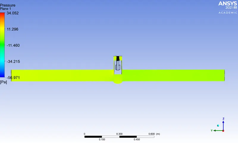
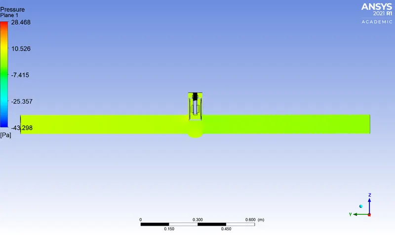
3) From the pressure contours the first region or the inlet part or the region before the gate disc is always at a higher pressure compared to the region after the gate disc due to inlet pressure of 10 bar.
4) At the outlet since there is no restriction in the movement of flow the pressure is absorbed to be 0 so the change in pressure drop across different value is negligible and is equal to 10 bar.
5) Mass flow rate, Kv and Cv are minimum for lowest opening of the gate disc and the value is maximum for all for highest opening i.e 80 mm.
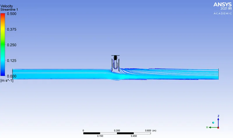
6) The region where the flow just exits the gate disc was observed to be the highest velocity region in the flow.
7) Parametric study is a very useful technique to carry out simulations with different parameters for the same study efficiently while saving time and computational power.
_ _ _ _ _ _ _ _ _ _ _ _ _ _ _ _ _ _ _ _ _ _ _ _ _ _ _ _ _ _ _ _ _ _ _ _ _ _ _ _ _ _ _ _ _ _ _ _ _ _ _ _ _ _ _ _ _ _ _ _ _ _ _ _ _ _ _ _ _ _ _ _ _ _ _ _
References-
https://en.wikipedia.org/wiki/Flow_coefficient
https://en.wikipedia.org/wiki/Gate_valve