Week 1- Mixing Tee
Aim: To set up a steady-state simulation to compare the mixing effectiveness of Mixing Tee when hot inlet temperature is 360C & the Cold inlet is at 190C for the following cases-
1. Case 1-
a) Short mixing tee with hot velocity of inlet 3 m/s.
b) Momentum ratio of 2 & 4
2. Case 2-
a) Long mixing tee with hot velocity of inlet 3 m/s.
b) Momentum ratio of 2 & 4
Introduction: To simulate steady-state simulation for the effectiveness of mixing tee using Ansys Fluent.
For case 1 short mixing tee
Viscous model used- K-Epsilon
hot inlet velocity= 3m/s
subcase 1:
Momentum ratio =2 which implies cold inlet velocity = 6m/s
hot inlet temperature= 36 degrees
cold inlet temperature= 19 degrees
subcase 2:
Momentum ratio =4 which implies cold inlet velocity = 12m/s
hot inlet temperature= 36 degrees
cold inlet temperature= 19 degrees
For case 2 Long mixing tee
Viscous model used- K-Epsilon
hot inlet velocity= 3m/s
subcase 1:
Momentum ratio =2 which implies cold inlet velocity = 6m/s
hot inlet temperature= 36 degrees
cold inlet temperature= 19 degrees
subcase 2:
Momentum ratio =4 which implies cold inlet velocity = 12m/s
hot inlet temperature= 36 degrees
cold inlet temperature= 19 degrees
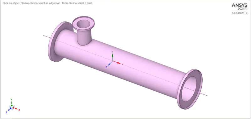
Theory: A mixing tee is a device that is used to mix fluids in a required proportion to attain a desirable velocity and temperature at the outlet by predetermining the inlet conditions. Mixing is a process that facilitates heat or mass transfer between different streams of fluid. Most industrial process's involving fluids require mixing at different extents, a mixing tee is extensively used in the HVAC industry to get the right amount of refrigeration in an air-conditioner.
Solving and modeling process-
1) CAD Model Cleanup using SpaceClaim-
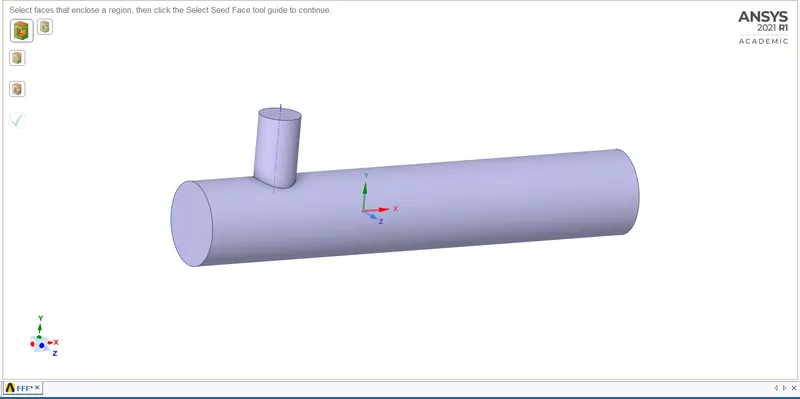
The .stl files of the mixing tee are imported into Spaceclaim to extract the actual fluid flow volume-
The extracted volume is shown below-
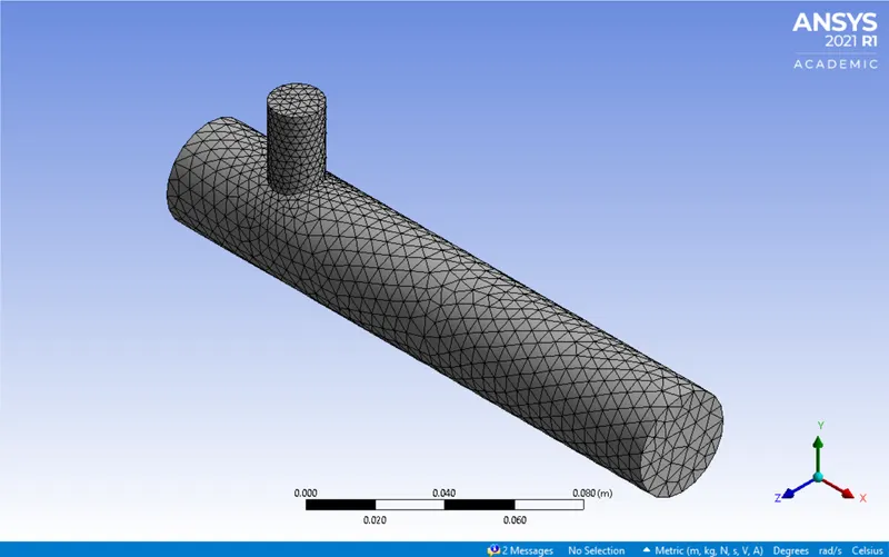
2) Meshing in Ansys mesh
Default element size- 1.0211e-002 m
Setup- In this, we set up the inlet & outlet boundary conditions. A suitable turbulent model k-omega or k-epsilon model will be used. The no. of iterations will be set up after that the case will be initialized at t=0 then the model will be run.
Post-processing- In this phase different planes will be set up to acquire the different parameters (temperature, velocity pressure), contours, and line plots.
CASE 1- SHORT TEE
For momentum ratio 2,
Hot inlet velocity=3 m/s
Cold inlet velocity= 6 m/s
Hot inlet temperature=36 C
Cold inlet temperature= 19 C
Mesh quality
Element size- 0.0015 m
No. of nodes- 41699
No. of elements- 211328
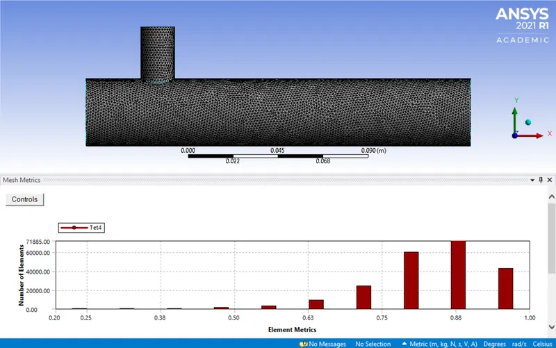
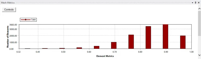
Since the mesh metric which tells us the quality of mesh was used, we can see that the no. of low-quality mesh are minimum and most of the mesh lie in the 0.7 - 1 region so this mesh is acceptable.
Turbulence model used- k-epsilon-realizable- Standard wall functions
Post-process
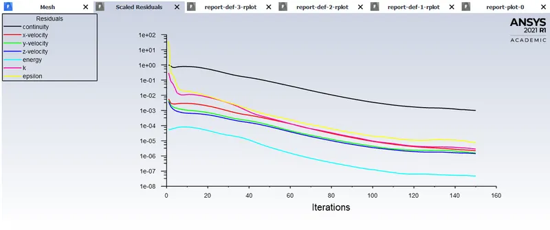
Residual plot
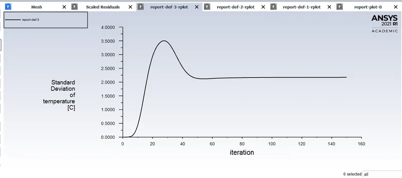
Standard deviation of Temperature
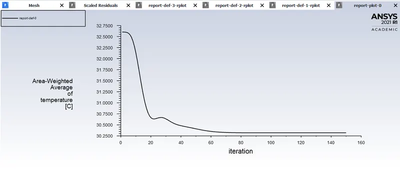
Temperature line Plot
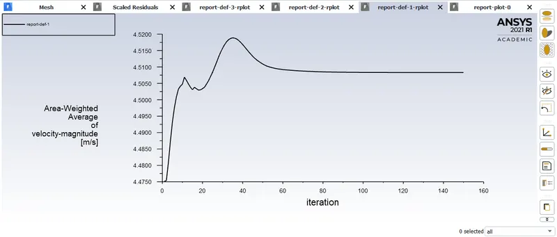
Velocity line plot
Contour plots
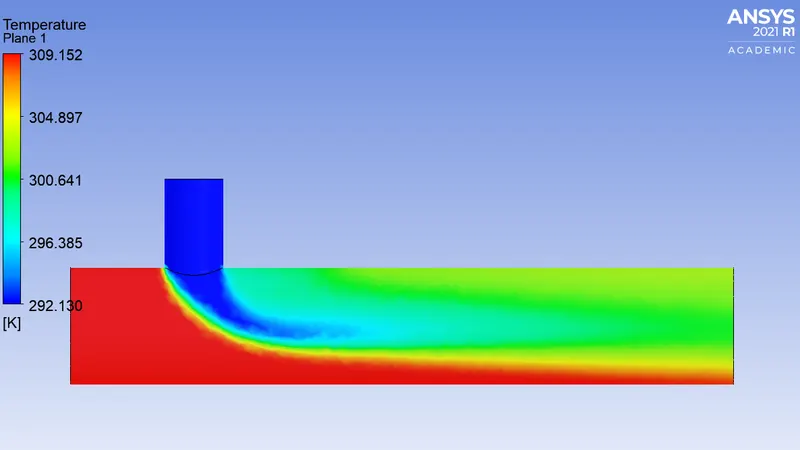
Temperature
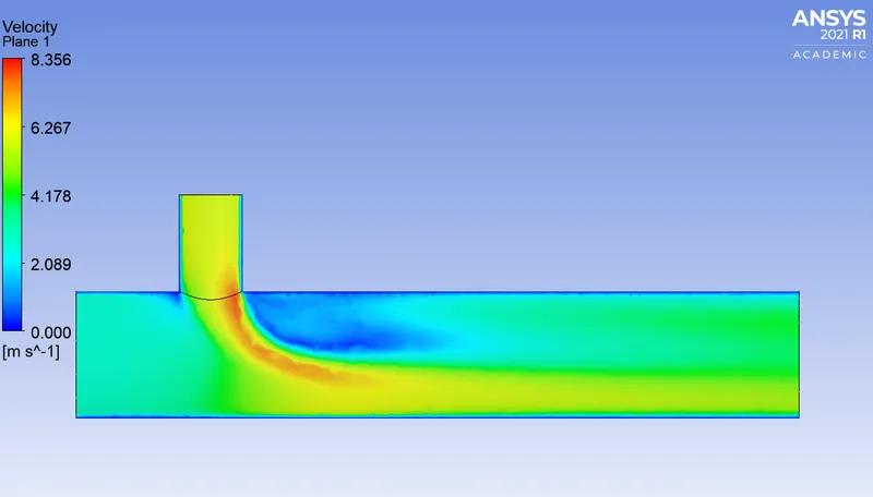
Velocity
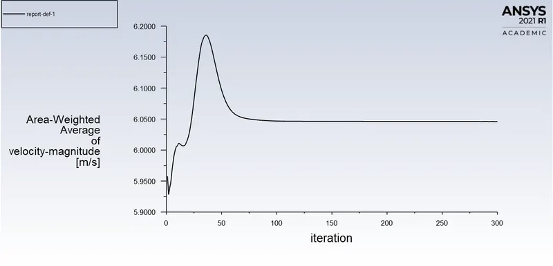
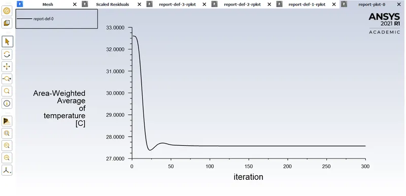
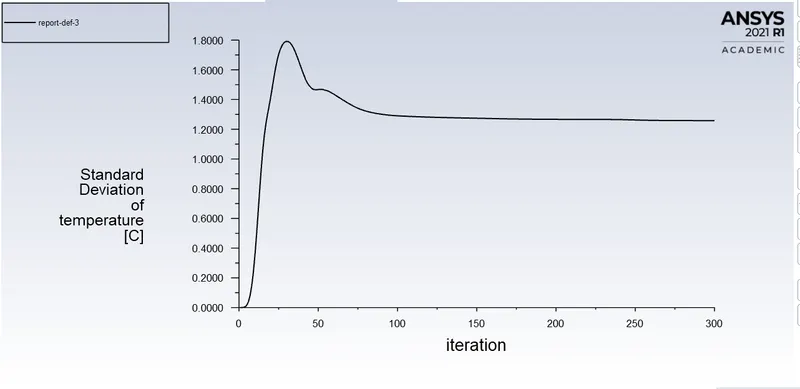
For momentum ratio = 4
Hot inlet velocity=3 m/s
Cold inlet velocity= 12 m/s
Hot inlet temperature=36 C
Cold inlet temperature= 19 C
Mesh quality
Element size- 0.0015 m
No. of nodes- 41699
No. of elements- 211328
Mesh metrics same as the above one
Turbulence model used- k-epsilon-realizable- Standard wall functions
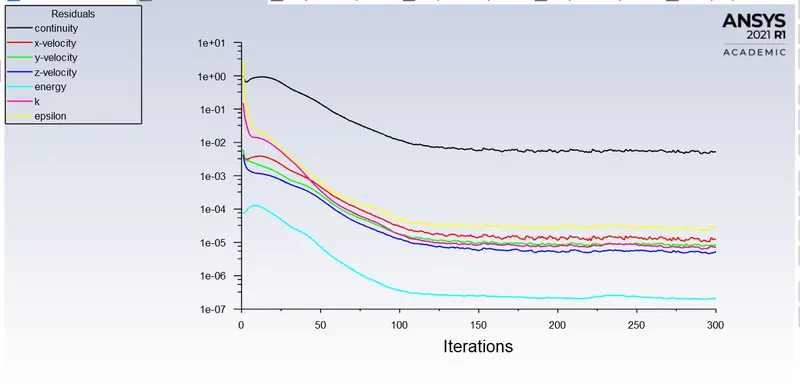
Residuals
Velocity line plots
Temperature line plots
Standard deviation of temperature
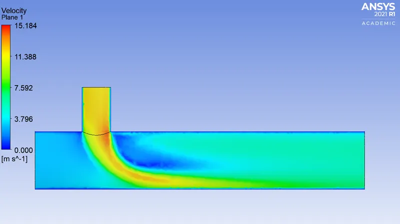
Contour plots
Velocity
Temperature
CASE 2- LONG TEE
For momentum ratio 2,
Hot inlet velocity=3 m/s
Cold inlet velocity= 6 m/s
Hot inlet temperature=36 C
Cold inlet temperature= 19 C
Mesh quality
Element size- 0.0017 m
No. of nodes- 48758
No. of elements- 246158
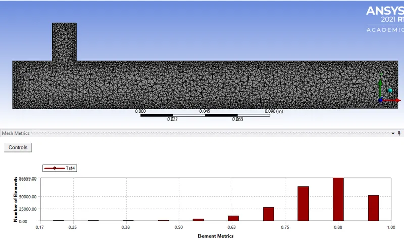
Since the mesh metric which tells us the quality of mesh was used, we can see that the no. of low-quality mesh are minimum and most of the mesh lie in the 0.75 - 1 region so this mesh is acceptable.
Turbulence model used- k-epsilon-realizable- Standard wall functions
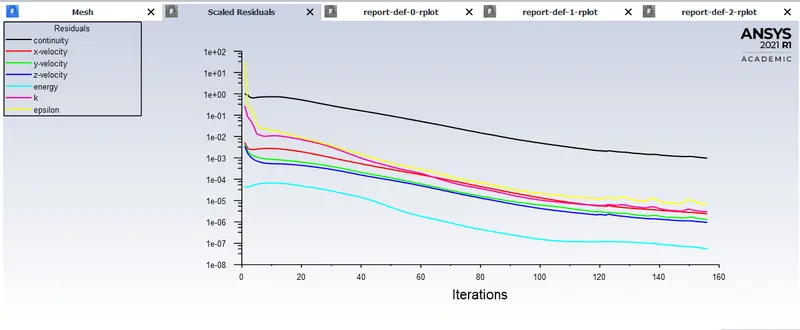
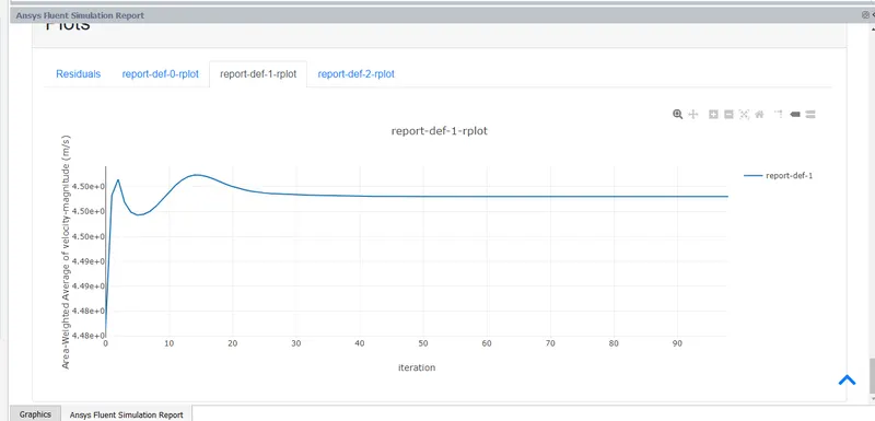
Residuals
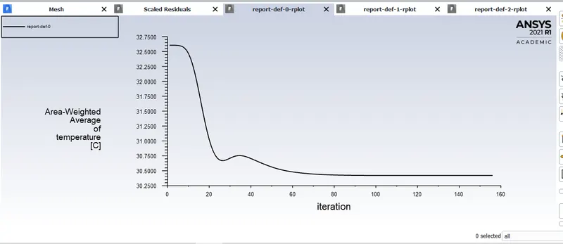
Temperature
Velocity
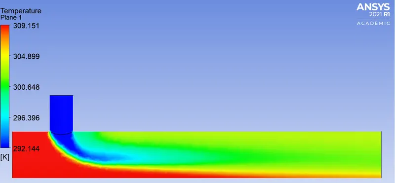
Contour plots
Temperature
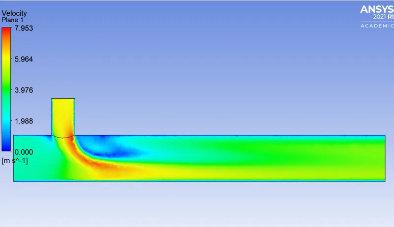
Velocity
For momentum ratio = 4
Hot inlet velocity=3 m/s
Cold inlet velocity= 12 m/s
Hot inlet temperature=36 C
Cold inlet temperature= 19 C
Mesh quality
Element size- 0.0017 m
No. of nodes- 48758
No. of elements- 246158
Mesh metrics same as above case.
Turbulence model used- k-epsilon-realizable- Standard wall functions
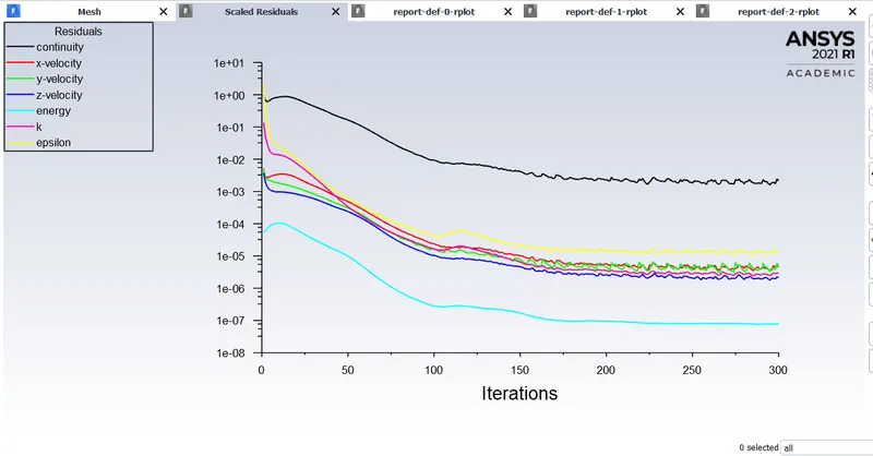
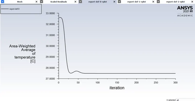
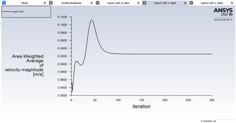
Residuals
Temperature
Velocity
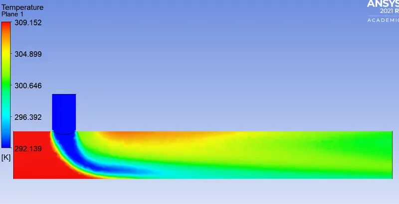
Temperature countour
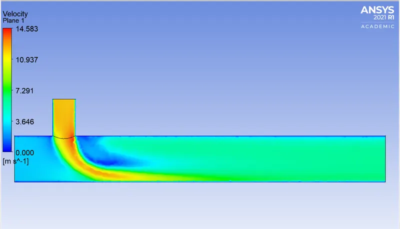
Contour Velocity
Comparisons of all outcomes- Outlet temperature
1) Short Tee Momentum ratio - 2 30.3 C
2) Short Tee Momentum ratio - 4 27.8 C
3) Long Tee Momentum ratio - 2 30.5 C
4) Long Tee Momentum ratio - 4 27.6 C
Result-
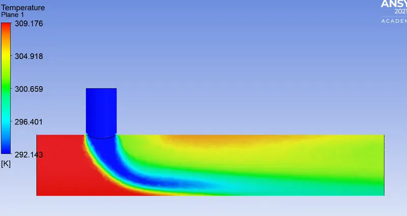
From the above cases, it is clearly visible that high inlet velocity of cold air favors high-temperature drop at the outlet mainly because it causes high turbulent mixture at the tee.
From the temperature contours of short tee over both momentum ratio's, some of the hot air doesn't mix with the cold seen at the lower end of the pipe and makes its way to the outlet thereby decreasing the mixing efficiency of the tee, whereas in a long tee we get a uniform mix of the air thereby giving us the favorable case.
In this particular simulation, the interactions which happen close to the wall are not significant and can be ignored which is evident from the velocity contour of all cases which shows near 0 velocities near the wall, so the k- epsilon model which predicts well for points away from the wall was chosen over k-omega which predicts the results well close to the wall.
So from the above simulations, the result can be drawn that a high velocity at the cold inlet with a long tee should be used to get the best mixing efficiency.