Week 4 - CHT Analysis on Exhaust port
CHT Analysis
Computational Fluid Dynamics (CFD) and more specifically conjugate heat transfer (CHT) analysis can accurately predict heat transfer by simultaneously solving all the relevant solid and flow field heat transfer processes, for example conduction through solids, free and forced convection in the gases/fluids and thermal radiation.
The CHT approach has an advantage over FE thermal analyses in that wall heat transfer coefficients and their local variations on surfaces are directly calculated within the model rather than based on simplified empirical calculations. The CHT approach, therefore, has benefits for those applications where heat transfer is either non-uniform or difficult to calculate empirically.
The Conjugate Heat Transfer (CHT) analysis type allows for the simulation of heat transfer between solid and fluid domains by exchanging thermal energy at the interfaces between them. Typical applications of this analysis type exist as, but are not limited to, the simulation.
Simulation
Geometry setup-
The below geometry was used to perform the analysis, it has 4 inlet which converge into 1 outlet.
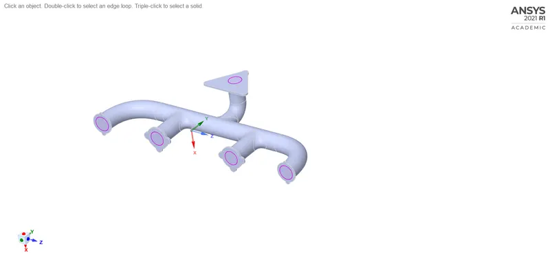
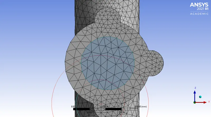
The fluid and solid volumes were extracted and the share topology feature was enabled so that data is exchnaged between the 2 volumes and a conformal mesh is obtained. A conformal mesh in CHT is important because the heat has to flow from fluid to solid volume and for it to properly calculate the parameters it should be able to extract data from each other, a conformal mesh is one in which the faces of the volume elements meet up and align properly with respect to each other.
This is how a conformal mesh looks like-
Meshing-
Baseline Mesh-
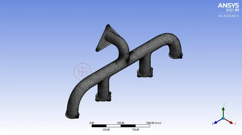
Element size- 150 mm
Statistics-
Nodes- 27378
Elements- 137315
Refined Mesh
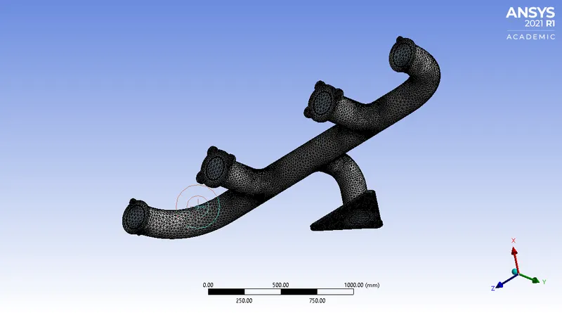
Element Size- 150 mm
Body sizing of solid volume element size- 10mm
Inflation Layers-
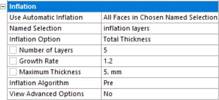
Statistics-
Nodes- 112575
Elements- 372053
Inflation layer-
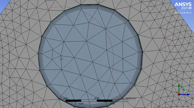
Solver Setup
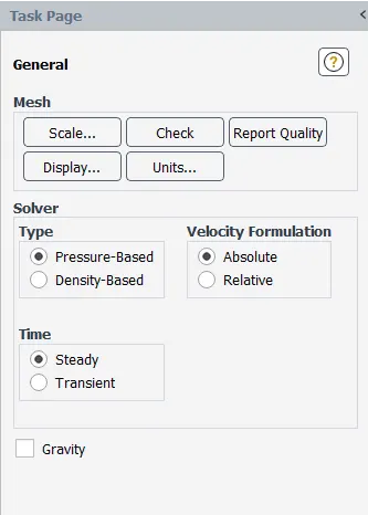
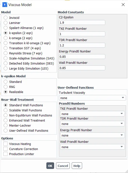
In order to maintain the appropriate y+ value the k-epsilon realizable model with near wall treatment as standard wall functions was used as the occurrences which happen near the wall is important to us and we need an accurate solution in that region.
Material properties-
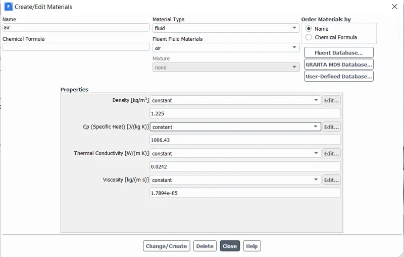
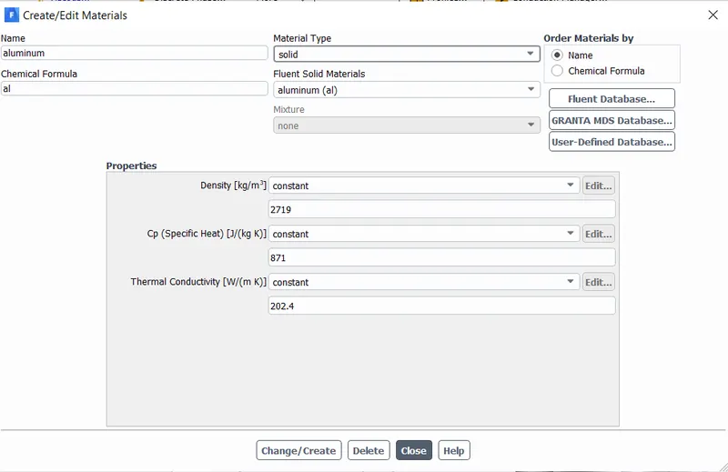
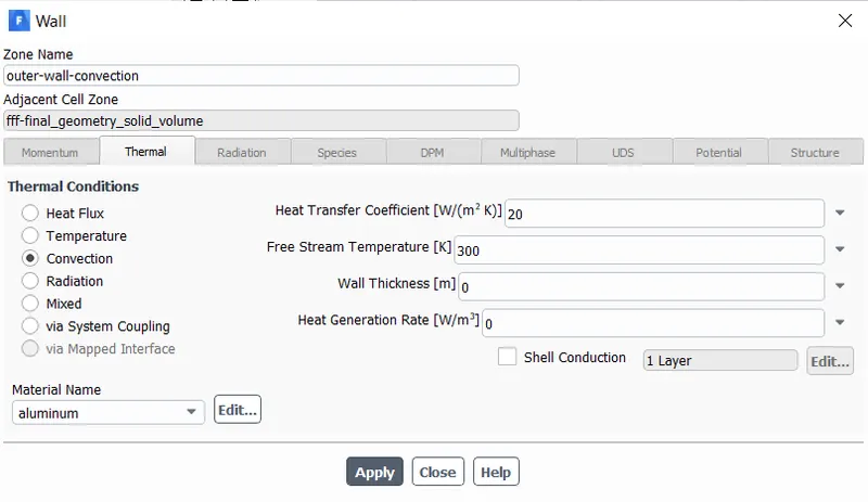
Boundary conditions-
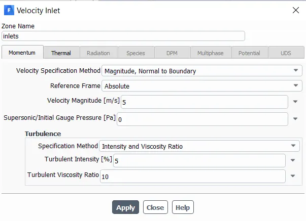
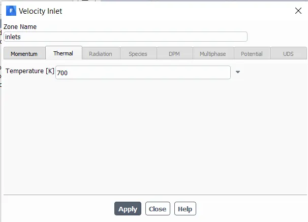
Solution-
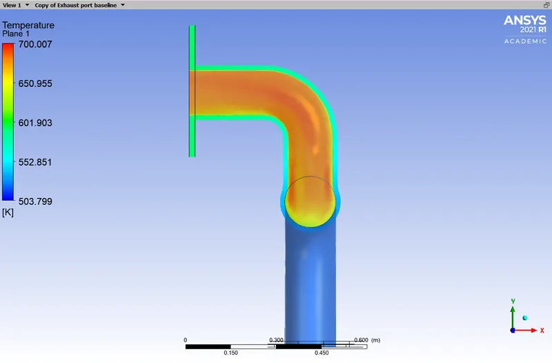
Temperature Plane-
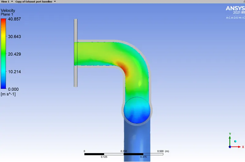
Velocity Plane-
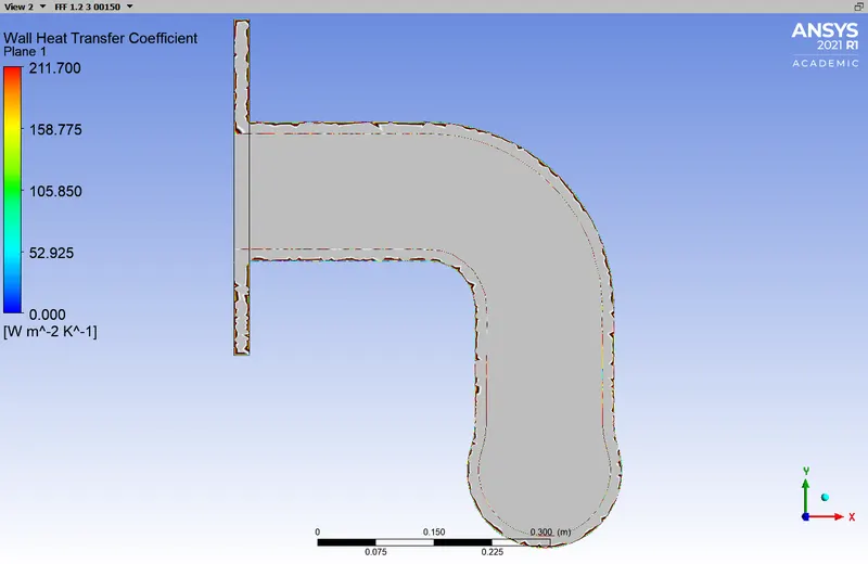
Heat Transfer coeeficient
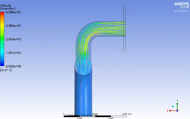
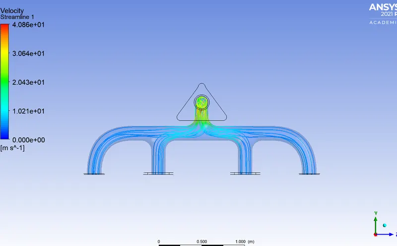
Streamlines
The value of heat transfer coefficient and wall heat flux was found using the probe and the value is as follows-
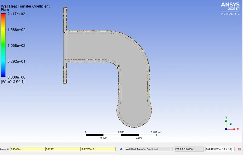
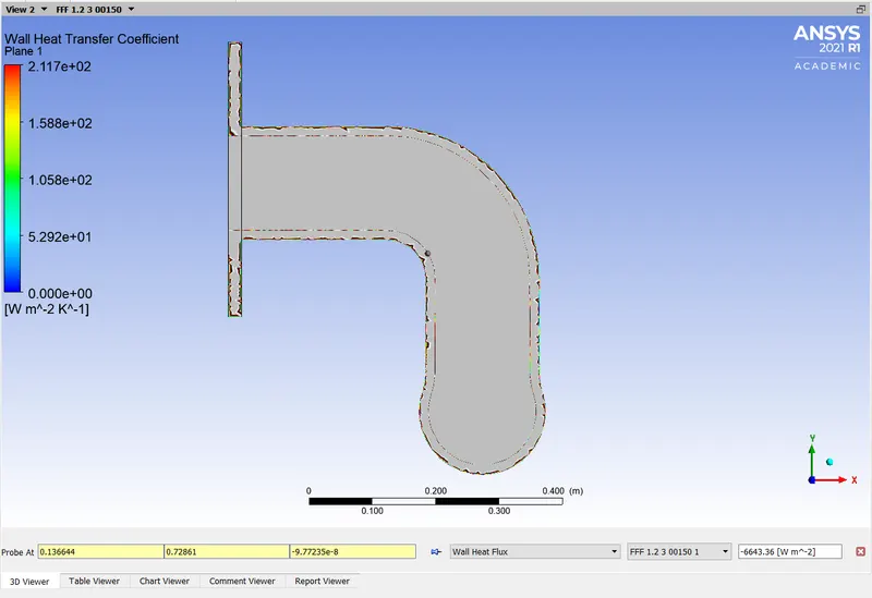
The result of CHT analysis can be verified by various ways like-
1) Theoretical verification using nusselt no.
2) Alternate theoretical method.
3) Grid independency test.
Verification by theoretical method-
Data-
h out= 20 w/m^2 k
Temperature= 300 K
K wall = 209.45 w/mk
H inside= ?
Bulk temperature at node= 682.31
q at node= 6643.63 w/m^2k
L= 0.015 m
R= convection resistance out + wall resistance + convection resistance inside
R= 1/h out + L/K+ 1/H inside
After substitution the value of H in = 212.45 W/m^2 K
The theoretical value of the heat transfer coefficient is near to that what we obtained this error can be minimized by improving the mesh even more.
Factors on which the accuracy of the predictions depend on are-
1. Element size
2. Refinement in specific regions.
3. Appropriate viscous and solid model settings.
4. Boundary condition settings.
5. Maintaining y+ value