Week 9 - Parametric study on Gate valve.
Aim-parametric study of gate valve
Objective-
Perform simulation at different lift
Calculate flow coefficient and flow factor
Mass flow rate at output
Introductions-
Gate valves are primarily designed to start or stop the fluid flow, and when a straight-line flow of fluid and minimum restriction to flow is needed. In service generally, this valve is fully open or fully closed.
The disk of a Gate valve is completely removed when the valve is fully open; the disk is fully drawn up into the valve Bonnet. This leaves an opening for flow through the valve at the same inside diameter as the pipe system in which the valve is installed. A Gate valve can be used for a wide range of liquids and provides a tight seal when closed.
Advantages: Good shutoff features, Gate valves are bidirectional and therefore they can be used in two directions, Pressure loss through the valve is minimal.
Disadvantages: They cannot be quickly opened or closed, Gate valves are not suitable for regulate or throttle flow, they are sensitive to vibration in the open state."
Gate valve
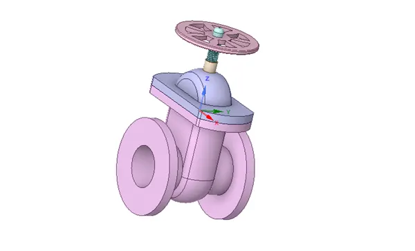
Gate valve components
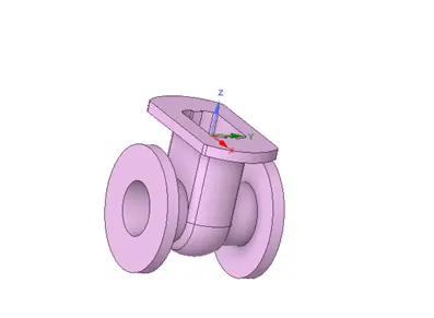
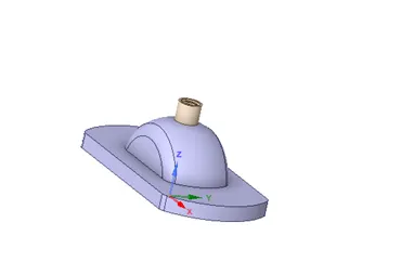
Bottom-- The valve body is the main pressure-retaining part, that also holds other parts named as disc and stem. This also provides passage to flow from the valve, its end connection is piping this end can be but welding type, threaded, and many more depends upon the size and pressure of the piping system.
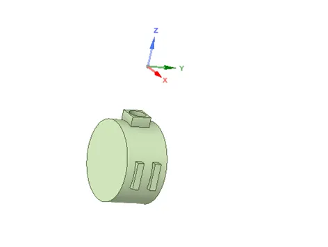
Gate disc-This is the part that allows throttles or stops flow on its position. In the case of a plug or ball valve, the disk is called a plug or ball. A disc is seated against the stationary wall seat or seats when the wall is in the closed position. It can be moved away from the valve seat by the motion of the valve string which the exception of the check valve and safety relief valve in which the disc is moved away from its seat by the fluid flow and pressure"
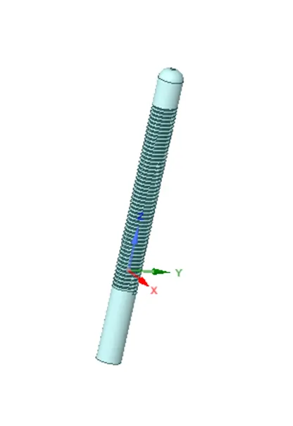
Spindle- stem or axis on which a valve is fastened and which transmits motion from outside of the steam or valve-chest to the valve proper within it."
Bonnet-Bonnets provide leakproof closure for the valve body. Gate valves may have a screw-in, union, or bolted bonnet. A screw-in bonnet is the simplest, offering a durable, pressure-tight seal. A union bonnet is suitable for applications requiring frequent inspection and cleaning. It also gives the body added strength. A bolted bonnet is used for larger valves and higher-pressure applications."
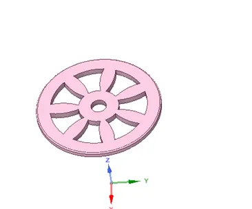
Handwheel-it is used for uplifting gate valve disc for valve opening with help of spindle
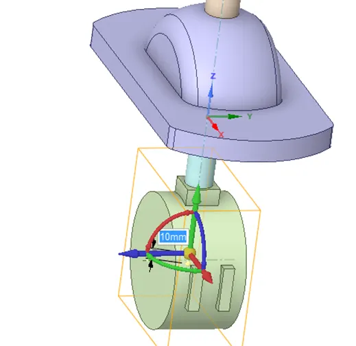
Parametric study-in this parametric study we lift gate disc by 10mm till 80mm and then compare the results. Parametric studies allow you to generate, execute and gather the results of multiple analyses that differ only in the values of some of the parameters
Geometry-
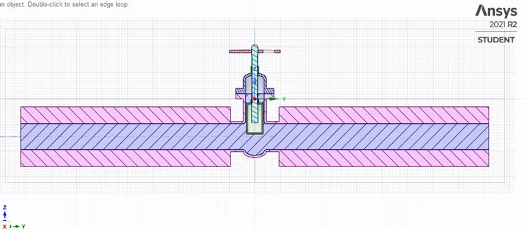
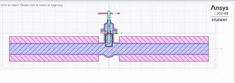
Model is imported in space-claim
By using move command, you will set your parameter
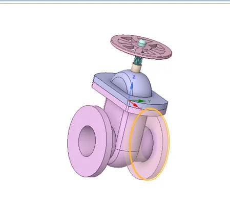
By using pull command, you will increase or pull body bottom by 800mm both side
Then extracted volume and all parts of gate valve is suppress for physics expect volume which extracted
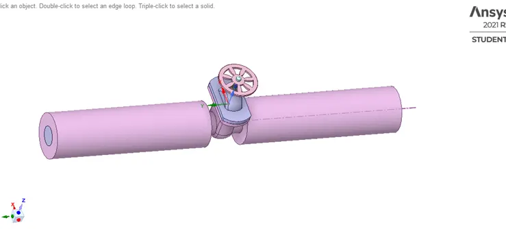
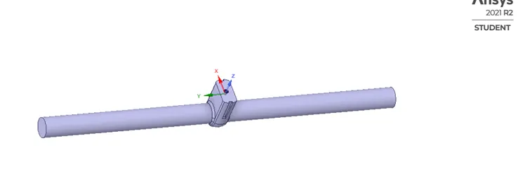
At different lift
10mm
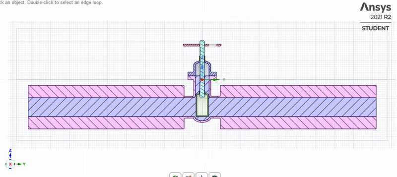
20mm
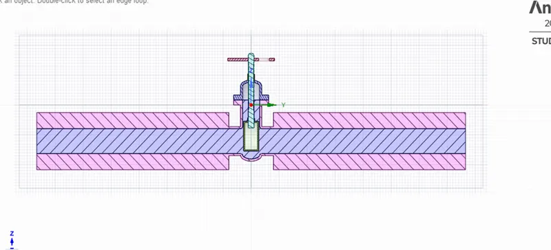
30mm
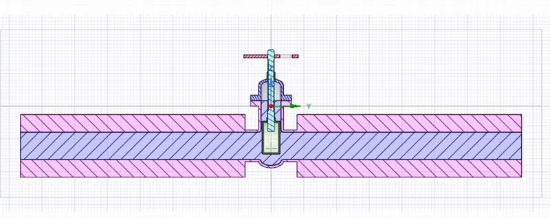
40mm
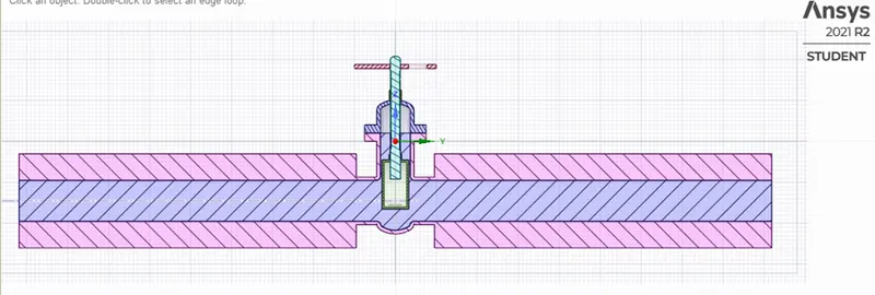
50mm
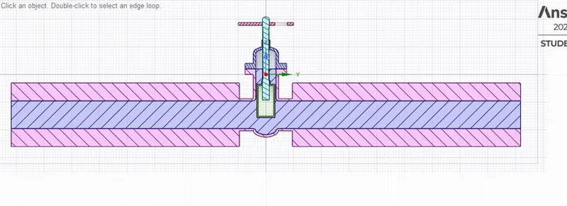
60mm
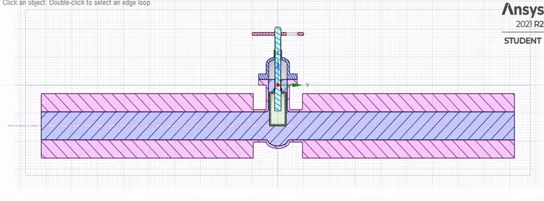
70mm
80mm
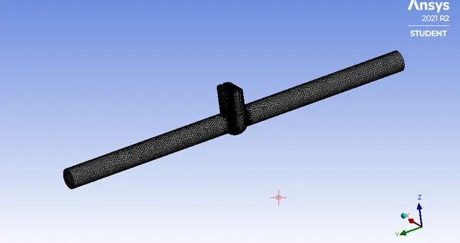
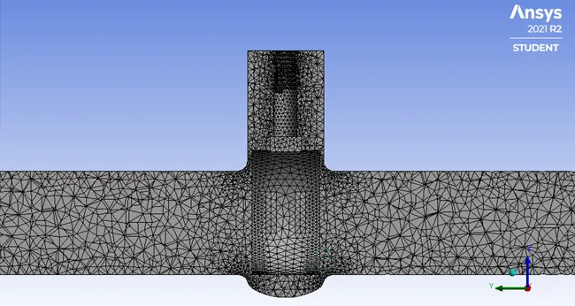
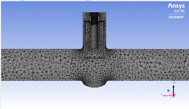
Mesh
Element size=10 mm
at different lift
10mm
Number of elements=191266
Number of nodes=40236
20mm
Number of elements=191685
Number of nodes=40080
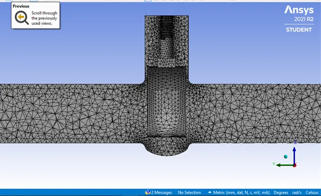
30mm
Number of elements=190796
Number of nodes=39864
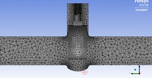
40mm
Number of elements=189714
Number of nodes=39600
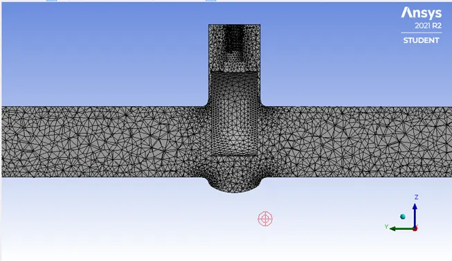
50mm
Number of elements=188221
Number of nodes=39323
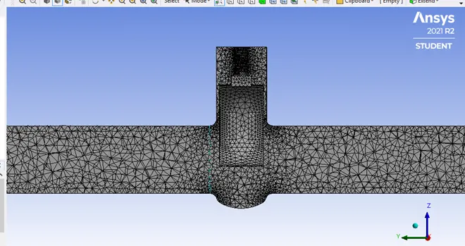
60mm
Number of elements=187116
Number of nodes=39167
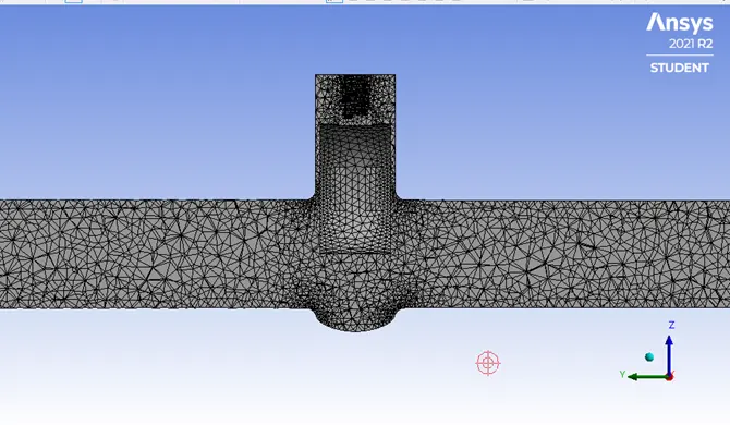
70mm
Number of elements=185339
Number of nodes=38945
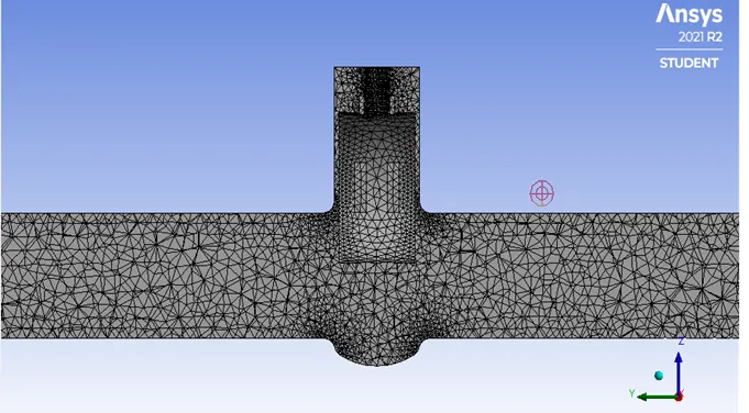
80mm
Number of elements=205903
Number of nodes=43232
Setup-
Slover type-pressure Based Solver
Time-Steady state
Gravity along Z directions= -9.81m/s^2
Model-viscous k-epsilon turbulant model-relizable-scalable wall Functions
Energy-turn off
Boundary condition- inlet pressure= 10pa
Outlet pressure= 0pa
Material properties- Water density=998.2kg/m^3
Viscosity =0.001003 kg/m-s
Method -coupled
Intilization-Standard intilizations
Velocity at inlet in y direction= 0.1415488 m/s
Calculation of reynold number for diciding turbulant model
- Re=ρVD/µ
V=velocity
D=Diameter
Re=Reynold number
µ=kinematic viscosity
Re=(998.2*0.1415488*0.1)/0.001003
Re=14087.13
Reynold number is greater than 2000 so flow is turbulent
Hence selected k-epsilon turbulent model
Solution
Residual at different lift
10mm
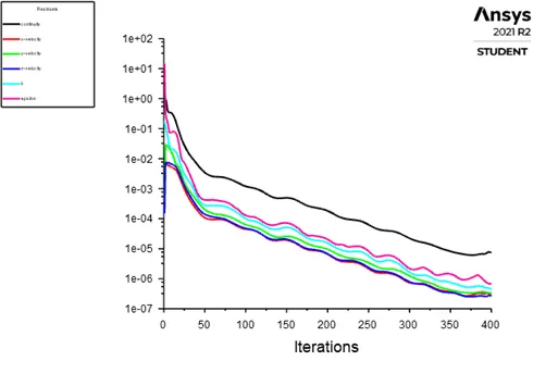
20mm
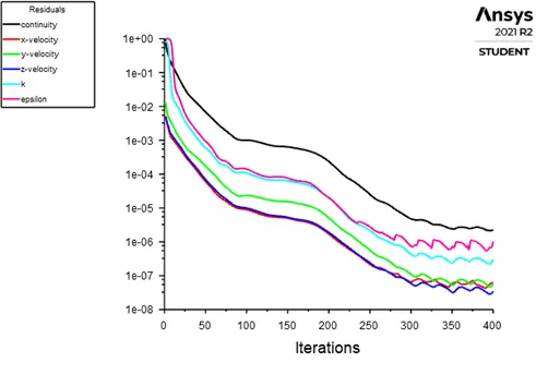
30mm
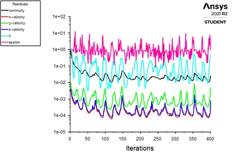
40mm
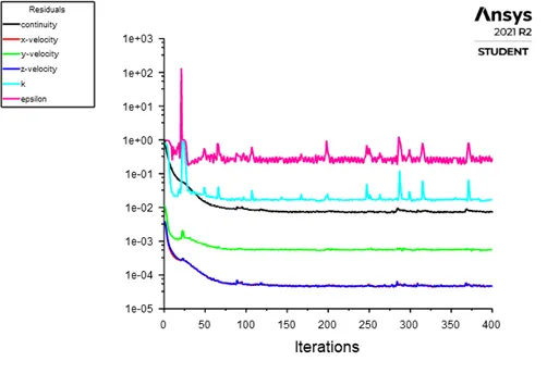
50mm
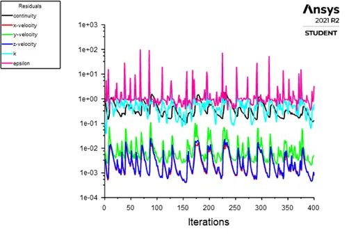
60mm
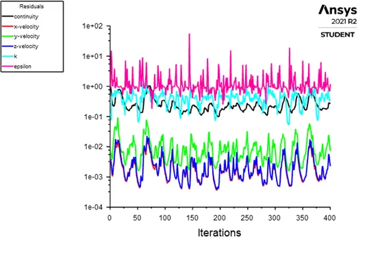
70mm
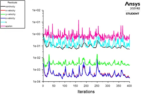
80mm
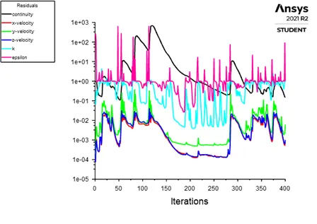
Mass flowrate at outlet at different lift
10mm
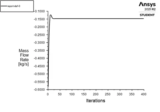
20mm
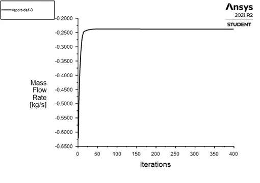
30mm
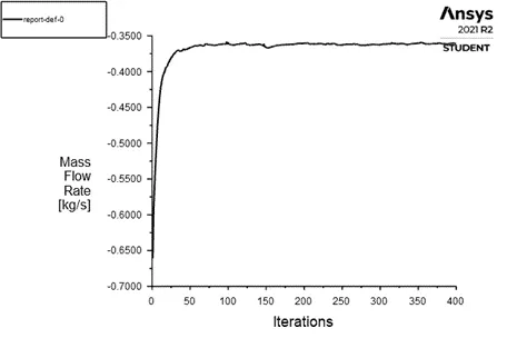
40mm
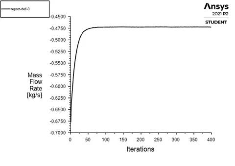
50mm
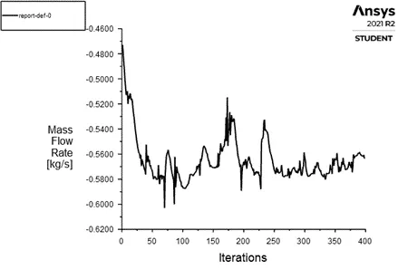
60mm
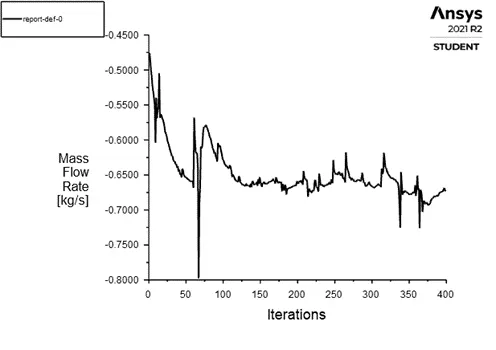
70mm
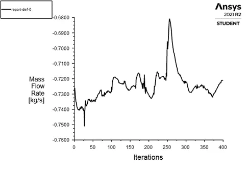
80mm
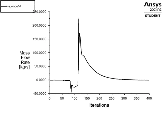
Velocity contour at different lift
10mm
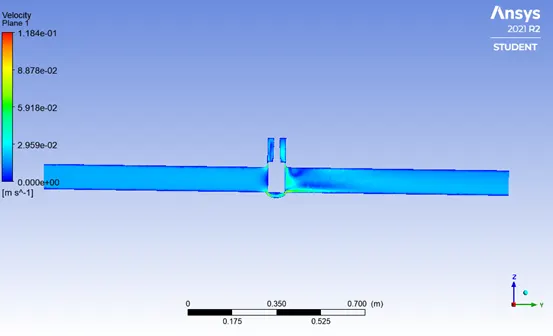
20mm
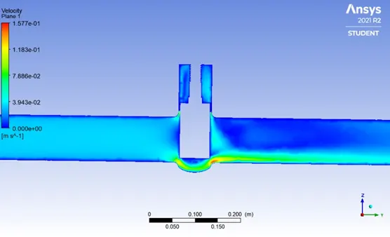
30mm
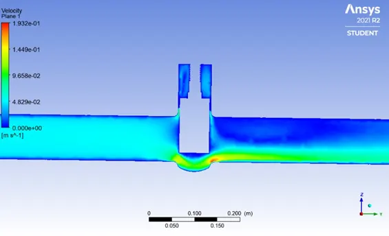
40mm
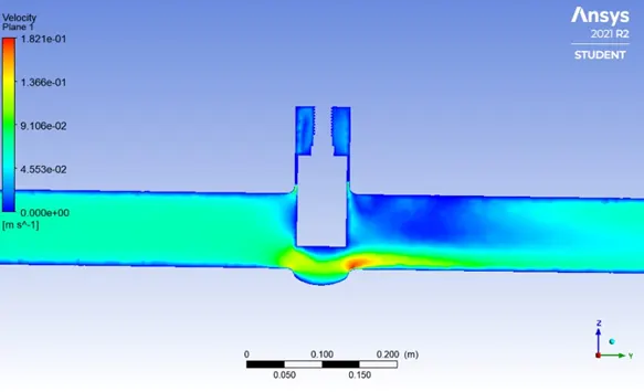
50mm
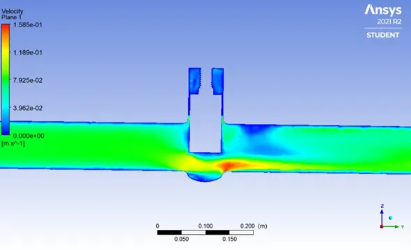
60mm
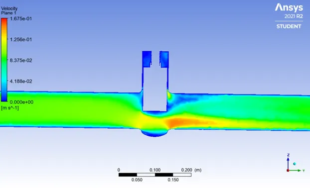
70mm
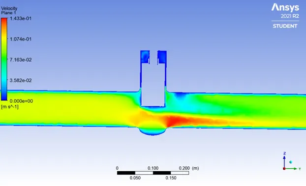
80mm
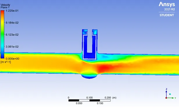
Velocity vector at different lift
10mm
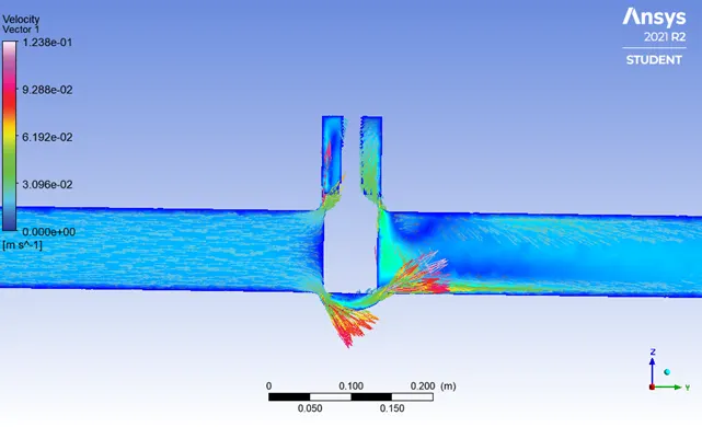
20mm
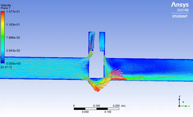
30mm
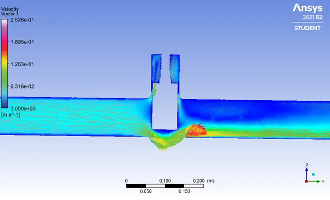
40mm
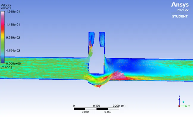
50mm
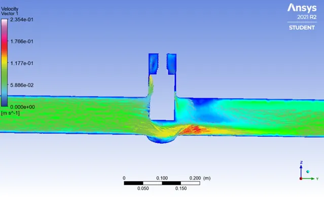
60mm
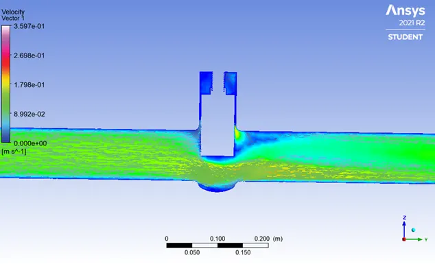
70mm
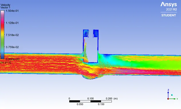
80mm
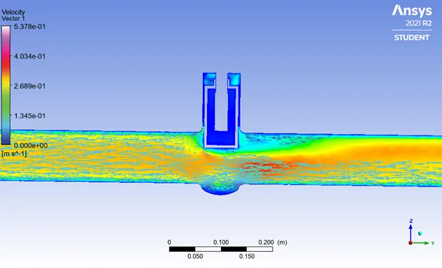
Table-mass flow rate
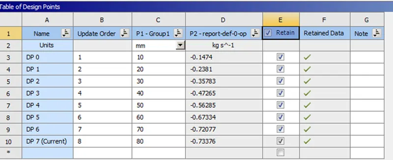
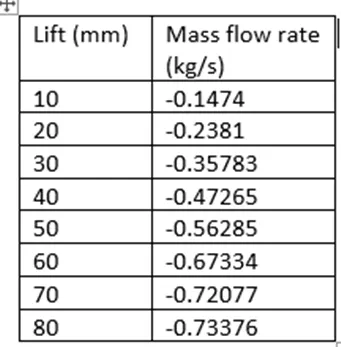
Note-negative mass flow rate means that mass is leaving our system
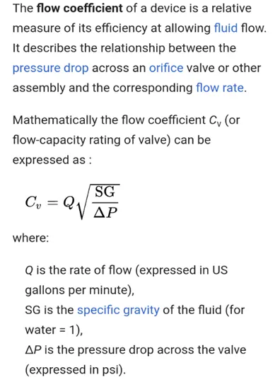
Flow coefficient
Flow Factor

Calculations of flow coefficient and flow factor
Flow coefficient
Cv=Q(SG/Δp)^0.5
For description you see paragraph for flow coefficient
Q= in gallons per minute
Δp= in psi
SG=1 for water
Convert mass flow rate in gallons per minute and pressure in psi
1 kg/s=15.85 gpm
10 pa=0.00145038 psi
For lift=10mm
Cv=15.85*0.1474*(1/0.00145038)^0.5
Cv=61.3458
Note calculate Cv at different lift by using this formula
Flow factor (Kv)
Kv= Q(SG/Δp)^0.5
Q= in m^3/hr
Δp= in bar
SG=1 for water
Convert mass flow rate in m^3/hr and pressure in bar
1kg/s=3.6 m^3/hr
10 pa=0.0001 bar
Kv=3.6*0.1474*(1/0.0001)^0.5
Kv=53.064
Note calculate Kv at different lift by using this formula
Cross check
Kv=0.865 * Cv
For lift=10mm
Cv=61.3458
Kv=0.865 * 61.3458
Kv=53.064 ----- compare this value with above value at it is exactly match
So our calculations is right
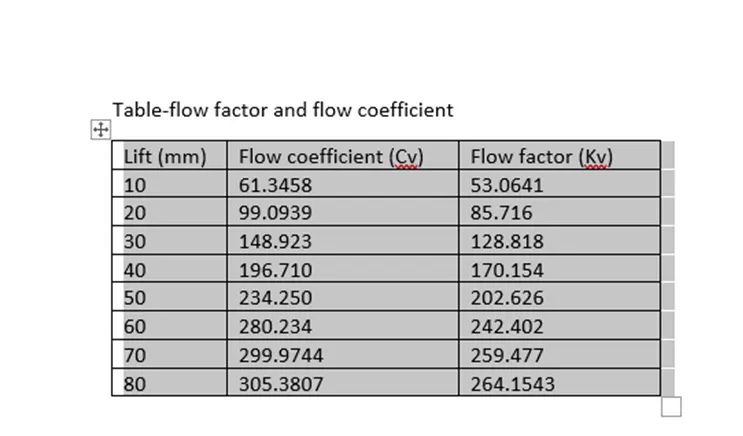
Table-flow factor and flow coefficient
Graphs
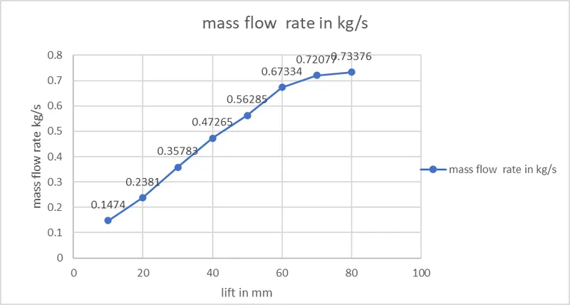
Mass flow rate vs lift of valve
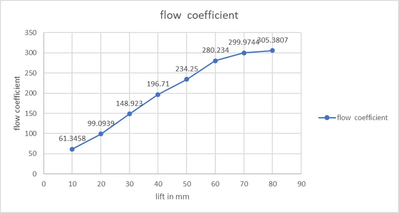
Flow coefficient vs lift of valve
Flow Factor vs lift of valve
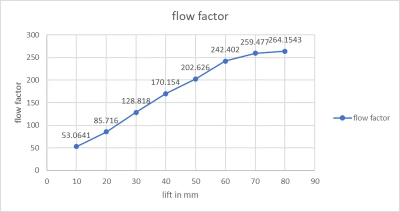
Note-negative mass flow rate means that mass is leaving our system and hence while plotting data I used positive sign
Conclusion-
- Mass flow rate at outlet increases as opening of valve increases
- Velocity contour smoothen out after lift i.e. valve opening increases
- Flow coefficient and flow factor also increases with increasing valve opening