Week 9 - Parametric study on Gate valve.
INTRODUCTION
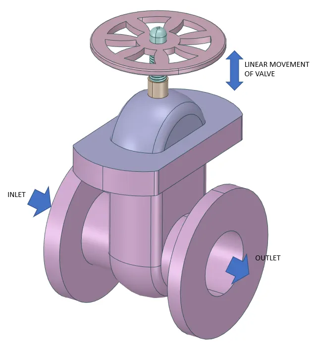
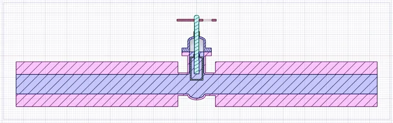
A gate valve controls the media's flow by lifting the gate (open) and lowering the gate (closed). A gate valve's distinct feature is the straight-through unobstructed passageway, which induces minimal pressure loss over the valve. The unobstructed bore of a gate valve also allows for a pig's passage in cleaning pipe procedures, unlike butterfly valves. Gate valves are available in many options, including various sizes, materials, temperature and pressure ratings, and gate and bonnet designs. A gate valve's main components are body, seat, gate, stem, bonnet, and actuator (Figure 2). The primary operation mechanism is straightforward. Turning the handwheel rotates the stem, which moves the gate up or down via the threads. They require more than one 360° turn to fully open/close the valve. Lifting the gate from the path of the flow, the valve opens. Lowering the gate to its closed position seals the bore resulting in a full closure of the valve.
For a gate valve, the relationship between the gate's vertical travel and the flow rate is nonlinear, with the highest changes occurring near shutoff. When used to regulate flow, the relatively high velocity of the flow at partial opening results in gate and seat wear, which along with possible vibrations of the gate, shortens the valve's service life.
GEOMETRY
FLUID VOLUME EXTRACTION
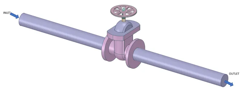
The fluid volume changes as the gate valve lift changes. For this, the verticle movement of the valve is parameterized.
After importing Geometry, hide the “Bottom” Part, so we can clearly see the “Gate Disc”.
- Then Select the “Gate Disc” component and move it in an upward direction by “10 mm” lift.
- To analyze the flow and its effects, we must allow the flow, and for that, we have given the 10 mm lift to the Gate Disc.
MESHING
Details:
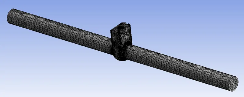
- Element Size: 5 mm
- of Elements: 597178
- of Nodes: 119029
- After Meshing, update it for further process and go for the Fluent Setup.

SETUP:-
- Here we have taken Pressure for inlet = 10 Pa.
- In the Viscous model, we have taken the K-Epsilon model.
- The reason behind choosing the K-Epsilon Viscous model is characteristic of the flow, which is turbulent.
- For Reynolds No. about 2000 and more, flow is turbulent. So we have taken the K-Epsilon Viscous model.
- But here, we have given Pressure Inlet, instead of Velocity Inlet. So knowing the velocity of the flow for correct Reynolds No. is required.
- So, to know the velocity of the flow, we have to go for initializing the solution.
- So, go to Solution, and select Standard Initialization, and Initialize from Inlet.
- After initialization, we can get the correct velocity and calculate the Reynolds No. and from that, we can decide on the appropriate viscous model.
Geometry
- Solver - Pressure Based
- Time - Steady State
Model:-
- Viscous - K -Epsilon (Realizable - Scaleable Wall Function)
Material:-
- Fluid - Water
Boundary Condition:-
- Inlet - Pressure Inlet ( Gauge Pressure - 10 Pa)
Method:-
- Scheme - Coupled
- Initialization - Standard from Inlet
- Number of Iteration - 300
PARAMETRIC STUDY
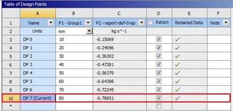
In the above image, the Parameterization of the valve to increase the flow area is given. The parameters are set for the study of different design points of the lift of the gate valve. On completion of the simulation, select “Parameter Set” and give input for different Design Points. Then Update all Design points and check all the results of different Design points.
Results:
Cases of lift of “Gate Disc” from 10% to 80% one by one.
- for all types of results, calculate the Flow coefficient and Flow Factor accordingly.
- Mass Flow Rate at Outlet, Flow Coefficient and Flow Factor and required Plots for each opening.
Flow Coefficient:
The flow coefficient of a device is a relative measure of its efficiency at allowing fluid flow. It describes the relationship between the pressure drop across an orifice valve or other assembly and the corresponding flow rate. Mathematically the flow coefficient Cv (or flow-capacity rating of the valve) can be expressed as:
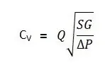
In more practical terms, the flow coefficient Cv is the volume (in US gallons) of water at 60 °F that will flow per minute through a valve with a pressure drop of 1 psi across the valve. The use of the flow coefficient offers a standard method of comparing valve capacities and sizing valves for specific applications that are widely accepted by the industry. The general definition of the flow coefficient can be expanded into equations modeling the flow of liquids, gases, and steam using the discharge coefficient.
Flow Factor:
The metric equivalent flow factor (Kv; commonly used in Europe and Asia) is calculated using metric units:
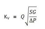
Kv can be calculated from Cv using the equation as given below:
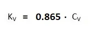
The Kv factor of a valve indicates "The water flow in m3/h, at a pressure drop across the valve of 1 kgf /cm2 when the valve is completely open.
Cases:
Here we will discuss all cases according to the opening percentage of “Gate Disc”.
According to the opening of the valve, given as lift of “Gate Disc” in mm, all 8 cases are named as given below:
- Case 1 = 10
- Case 2 = 20
- Case 3 = 30
- Case 4 = 40
- Case 5 = 50
- Case 6 = 60
- Case 7 = 70
- Case 8 = 80
Case 1
Gate valve lifted by 10 mm
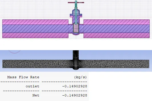
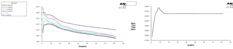
Residual and Mass Flow rate Plot
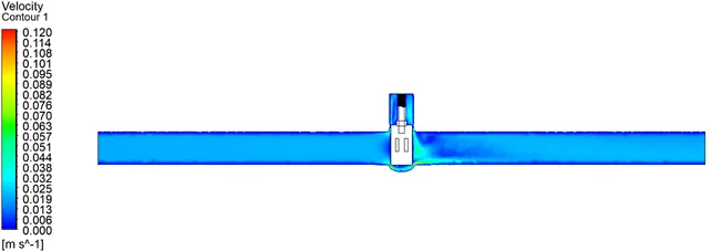
Velocity contour at midsection in ZY plane
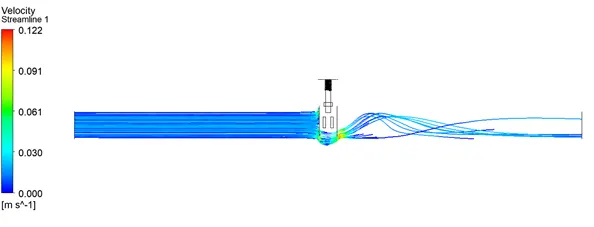
Velocity streamline
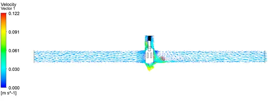
Velocity Vector
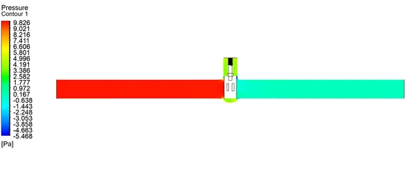
Pressure contour
Case 2
Gate valve lifted by 20 mm
Geometry
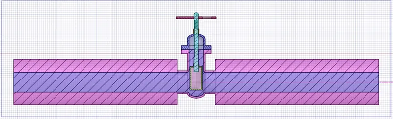
Meshing

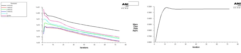
Residual and Mass Flow rate Plot
Results
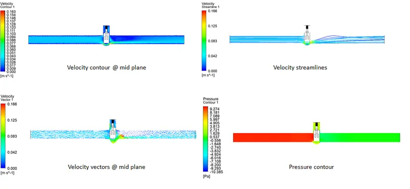
Case 3
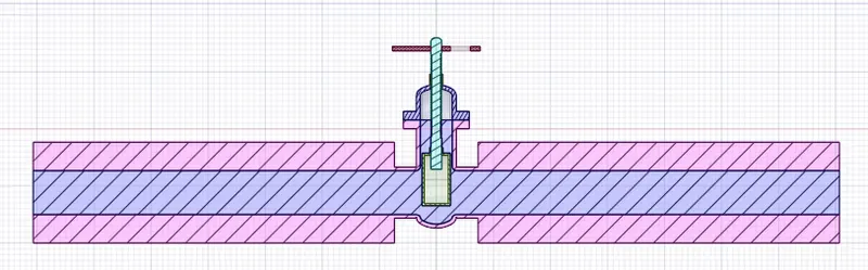
Gate valve lifted by 30 mm
Geometry
Meshing

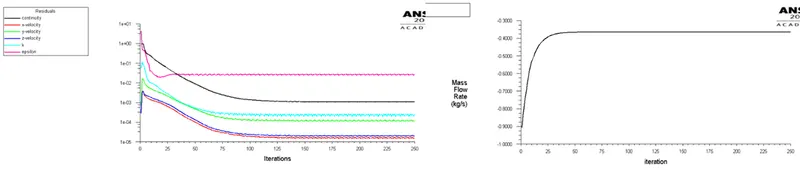
Residual and Mass Flow rate Plot
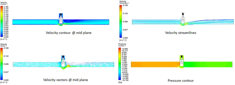
Results
Case 4
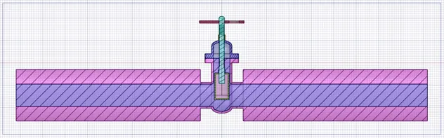
Gate valve lifted by 40 mm
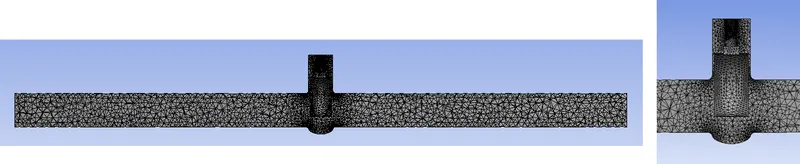
Meshing
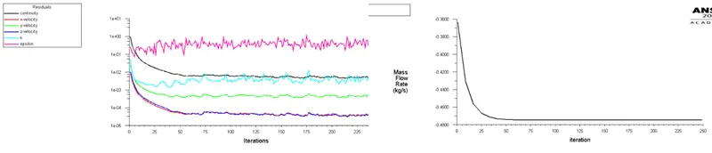
Residual and Mass Flow rate Plot
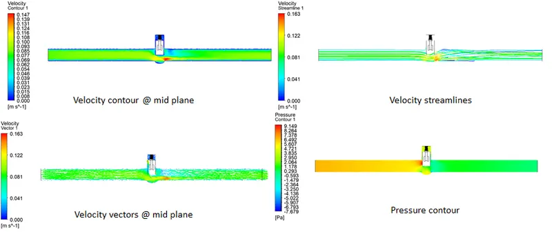
Results
Case 5
Gate valve lifted by 50 mm
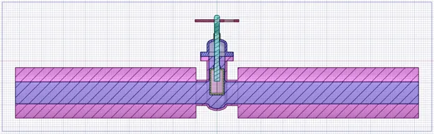
Geometry
Meshing

Residual and Mass Flow rate Plot
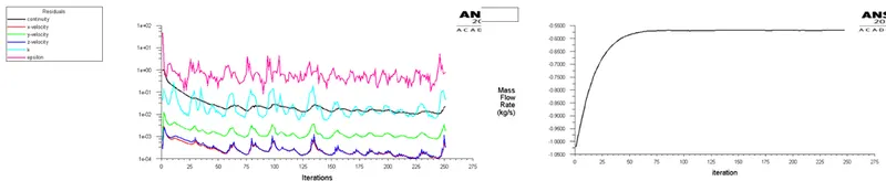
Results
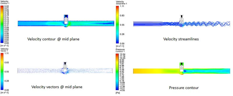
Case 6
Gate valve lifted by 60 mm
Geometry
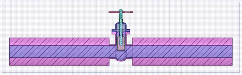
Meshing

Residual and Mass Flow rate Plot
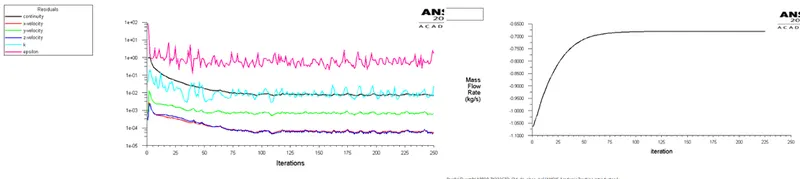
Results
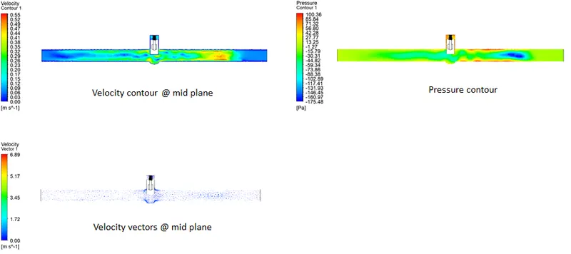
Case 7
Gate valve lifted by 70 mm
Geometry
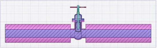
Meshing

Residual and Mass Flow rate Plot
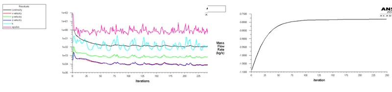
Results
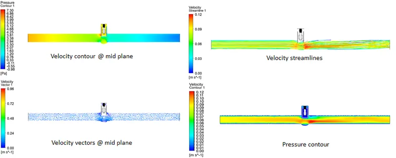
Case 8
The gate valve is lifted by 80 mm
Geometry
Meshing

Residual and Mass Flow rate Plot
Results
Flow factor Kv =0.865* Cv
Flow coefficient Cv= Kv/0.865
Results Statistics:
|
Case |
Mass flow rate (kg/s) |
Lift (mm) |
Flow coef. |
Flow factor |
|
Case 1 |
0.157 |
10 |
0.047 |
0.041 |
|
Case 2 |
0.241 |
20 |
0.076 |
0.065 |
|
Case 3 |
0.363 |
30 |
0.114 |
0.101 |
|
Case 4 |
0.472 |
40 |
0.149 |
0.129 |
|
Case 5 |
0.563 |
50 |
0.178 |
0.154 |
|
Case 6 |
0.643 |
60 |
0.203 |
0.176 |
|
Case 7 |
0.722 |
70 |
0.228 |
0.197 |
|
Case 8 |
0.785 |
80 |
0.249 |
0.215 |
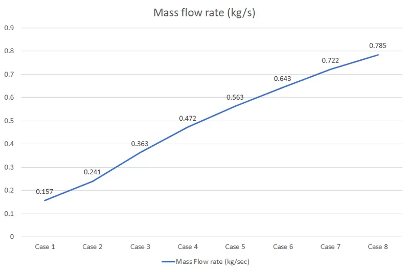
Mass flow rate graph for various cases
Conclusion:
- Mass flow rate gradually increases as the lift of the gate disc is increased.
- The variation of flow coefficient and flow factor with the opening of the valve is studied by using parametric.
- A parametric study is a time reducing option when studying the effects of changes of certain parameters on a system.
- Flow coefficient plays important role in the selection of valve and sizing of a valve, so calculating it is necessary.
- Flow coefficient also helps in computing the efficiency of the system and the effect of pressure on the system.