Week 9 - Parametric study on Gate valve.
AIM: GATE VALVE SIMULATION
For this challenge, you will have to perform a parametric study on the gate valve simulation by setting the opening from 10 % to 80%.
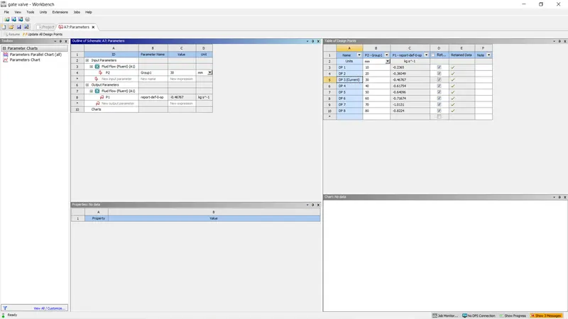
- Obtain the mass flow rates at the outlet for each design point.
- Calculate the flow coefficient and flow factor for each opening and plot the graph.
- Discuss the results of the mass flow rate and flow coefficient.
GATE VALVE:
A gate valve, also known as a sluice valve, is a valve that opens by lifting a barrier out of the path of the fluid. Gate valves require very little space along the pipe axis and hardly restrict the flow of fluid when the gate is fully opened. The gate faces can be parallel but are most commonly wedge-shaped.A gate valve is generally used to completely shut off fluid flow or, in the fully open position, provide full flow in a pipeline. Thus it is used either in the fully closed or fully open positions. A gate valve consists of a valve body, seat and disc, a spindle, gland, and a wheel for operating the valve.
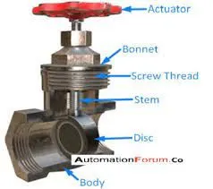
Gate valves are used to shut off the flow of liquids rather than for flow regulation. When fully open, the typical gate valve has no obstruction in the flow path, resulting in very low flow resistance. The size of the open flow path generally varies in a nonlinear manner as the gate is moved. This means that the flow rate does not change evenly with stem travel. Depending on the construction, a partially open gate can vibrate from the fluid flow.
Gate valves are mostly used with larger pipe diameters (from 2" to the largest pipelines) since they are less complex to construct than other types of valves in large sizes.
At high pressures, friction can become a problem. As the gate is pushed against its guiding rail by the pressure of the medium, it becomes harder to operate the valve. Large gate valves are sometimes fitted with a bypass controlled by a smaller valve to be able to reduce the pressure before operating the gate valve itself.
Gate valves without an extra sealing ring on the gate or the seat are used in applications where minor leaking of the valve is not an issue, such as heating circuits or sewer pipes.
Gate valves are used to shut off the flow of liquids rather than for flow regulation. When fully open, the typical gate valve has no obstruction in the flow path, resulting in very low flow resistance.
GATE VALVE DESIGN AND TYPES:
Bonnet
was primarily used for supporting the position of the Plug-time scroll up, scroll down to find it. No left and right But some manufacturers cut output to reduce the Bonnet Cost for the production and sale of the valve. The maintenance is also difficult. It is not to come and support the position of the Plug and Seat to meet constantly Lapping.
DISC
For a valve having a bonnet, the disk is the third primary principal pressure boundary. The disk provides the capability for permitting and prohibiting fluid flow. With the disk closed, full system pressure is applied across the disk if the outlet side is depressurized.
For this reason, the disk is a pressure-retaining part. Disks are typically forged and, in some designs, hard-surfaced to provide good wear characteristics. A fine surface finish of the seating area of a disk is necessary for good sealing when the valve is closed. Most valves are named, in part, according to the design of their disks.
The seat or seal rings provide the seating surface for the disk. In some designs, the body is machined to serve as the seating surface and seal rings are not used. In other designs, forged seal rings are threaded or welded to the body to provide the seating surface.
Valve Actuator
The actuator operates the stem and disk assembly. An actuator may be a manually operated hand wheel, manual lever, motor operator, solenoid operator, pneumatic operator, or hydraulic ram. In some designs, the actuator is supported by the bonnet. In other designs, a yoke mounted to the bonnet supports the actuator.
Except for certain hydraulically controlled valves, actuators are outside of the pressure boundary.Yokes, when used, are always outside of the pressure boundar
Stem
The stem, which connects the actuator and disk, is responsible for positioning the disk. Stems are typically forged and connected to the disk by threaded or welded joints. For valve designs requiring stem packing or sealing to prevent leakage, a fine surface finish of the stem in the area of the seal is necessary. Typically, a stem is not considered a pressure boundary part.
Connection of the disk to the stem can allow some rocking or rotation to ease the positioning of the disk on the seat. Alternately, the stem may be flexible enough to let the disk position itself against the seat. However, constant fluttering or rotation of a flexible or loosely connected disk can destroy the disk or its connection to the stem.
Two types of valve stems are rising stems and non-rising stems. These two types of stems are easily distinguished by observation. For a rising stem valve, the stem will rise above the actuator as the valve is opened. This occurs because the stem is threaded and mated with the bushing threads of a yoke that is an integral part of, or is mounted to, the bonnet.
There is no upward stem movement from outside the valve for a non rising stem design. For the non rising stem design, the valve disk is threaded internally and mates with the stem threads.
GEOMENTRY:
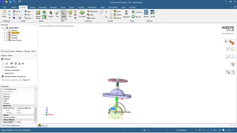
The fluid volume is extraacted. Go to prepare volume extract.
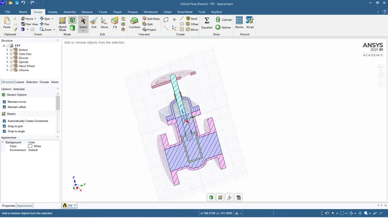
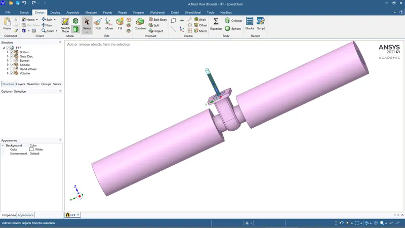
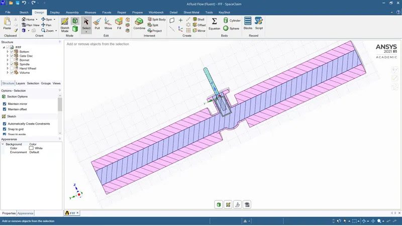
Disc lift of 10mm and the parametric study is created.
MESHING:
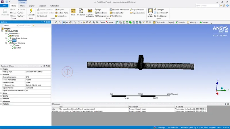
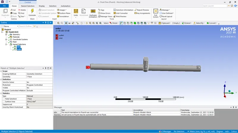
Meshing is done with base mesh value.
MODEL SETUP:
K-epsilon viscous model.
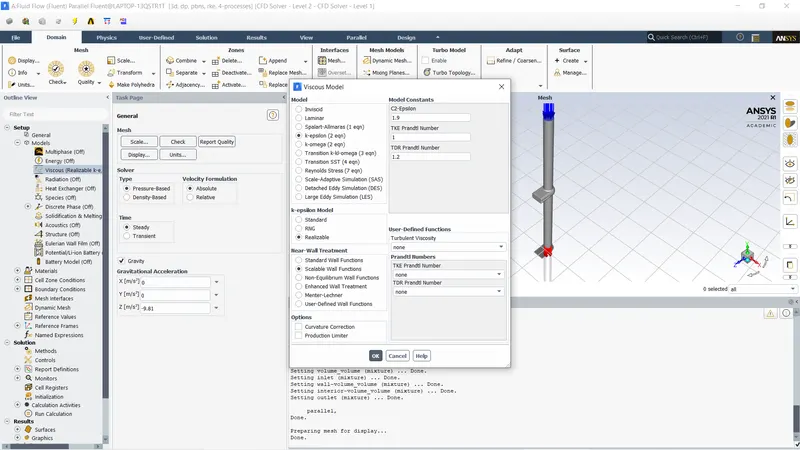
Fluid medium is water.
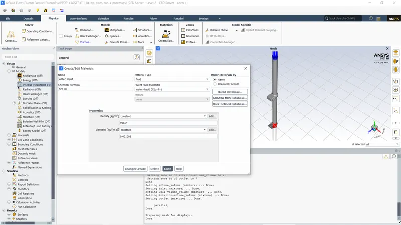
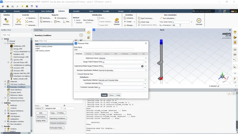
Inlet pressure of 10Pa.
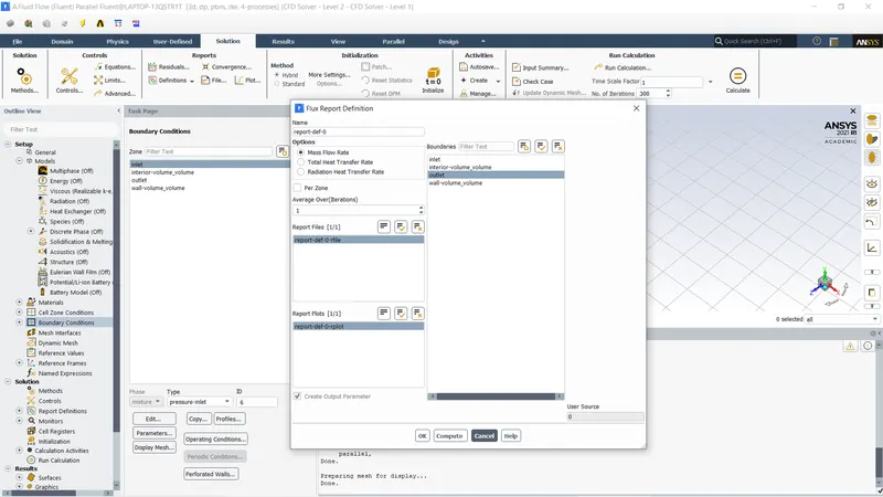
Once the input and the output parameters are parameterized. All the design point are created by 10% increase on lift and the design points are updated to calculate.
RESULT:
CASE 1: 10mm
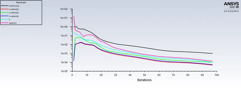
SCALE RESIDUAL:
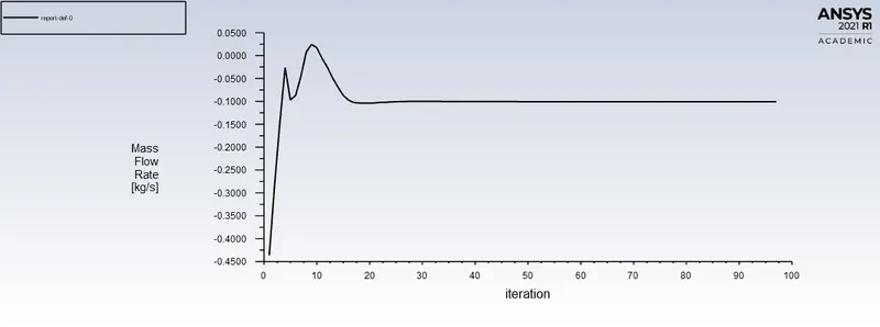
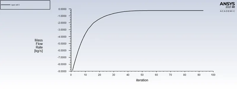
MASS FLOW RATE:
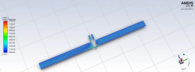
CONTOUR:
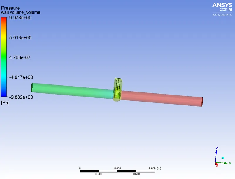
PRESSURE:
STREAMLINES:
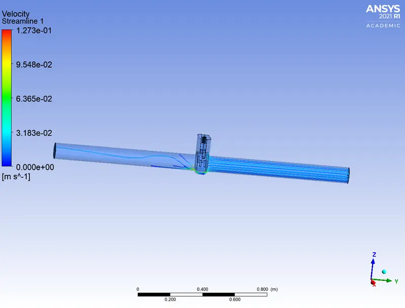
CASE 2: 20mm
SCALE RESIDUAL:
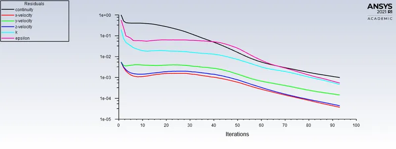
MASS FLOW RATE:
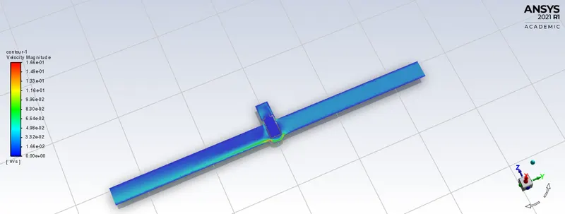
CONTOUR:
PRESSURE:
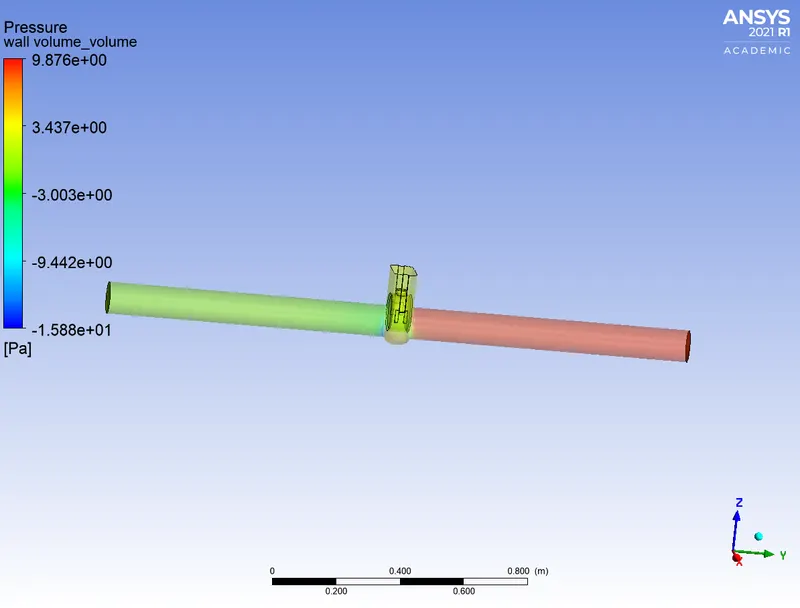
STREAMLINES:
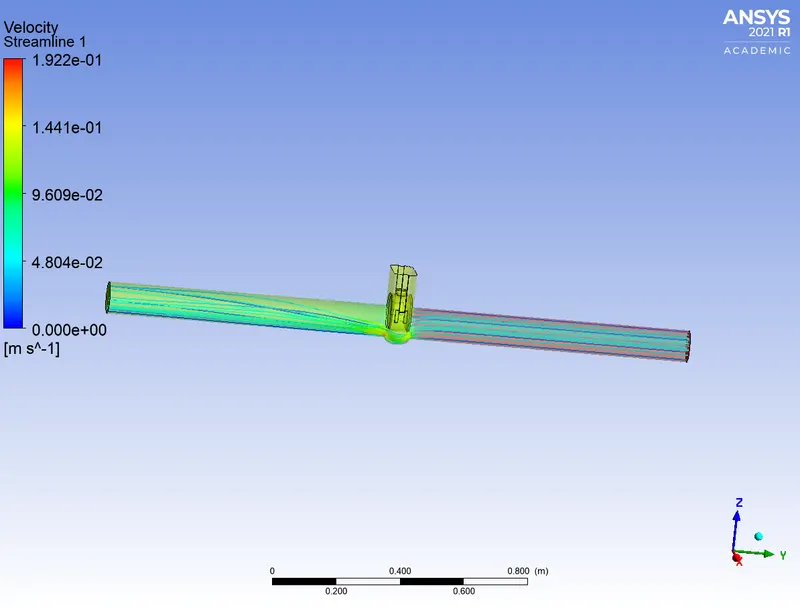
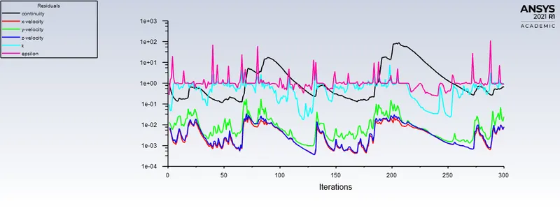
CASE 3: 30mm
SCALE RESIDUAL:
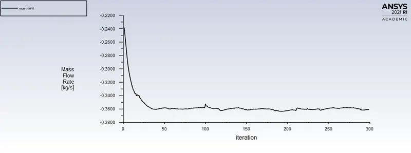
MASS FLOW RATE:
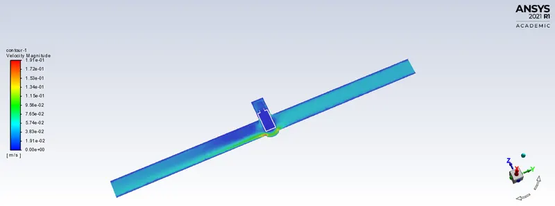
CONTOUR:
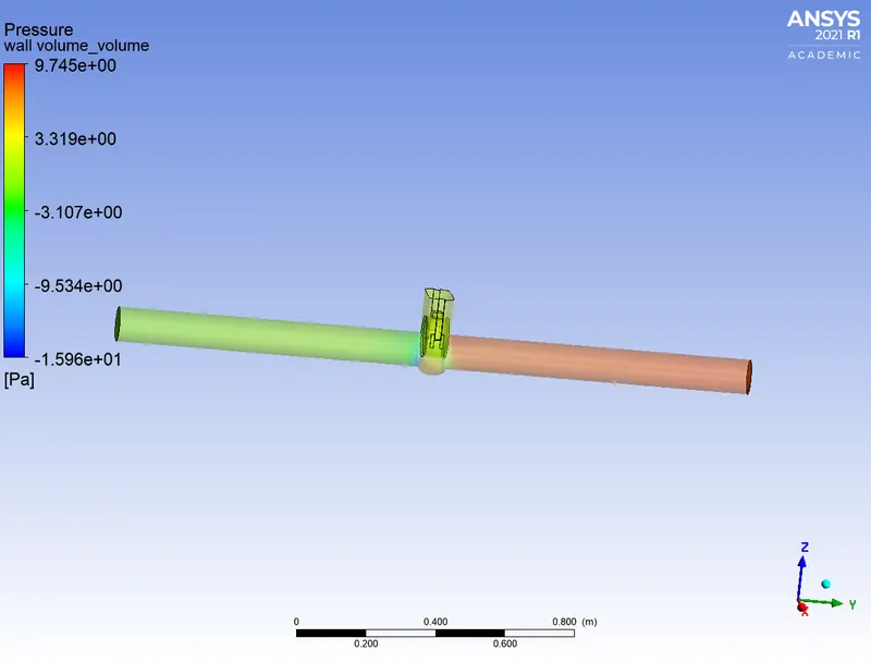
PRESSURE:
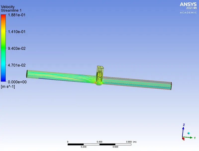
STREAMLINES:
CASE 4: 40mm
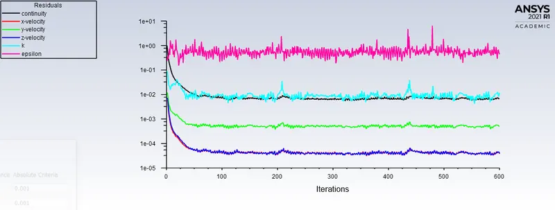
SCALE RESIDUAL:
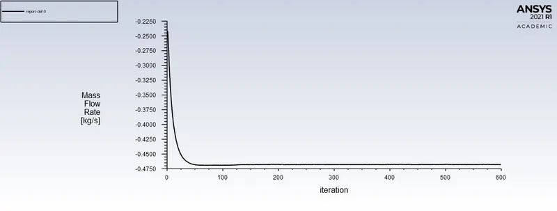
MASS FLOW RATE:
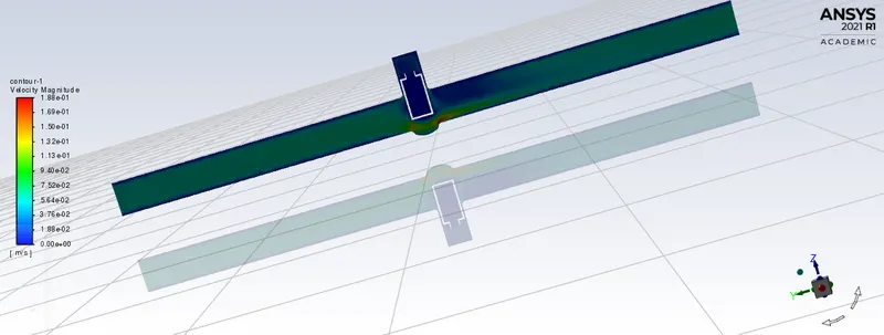
CONTOUR:
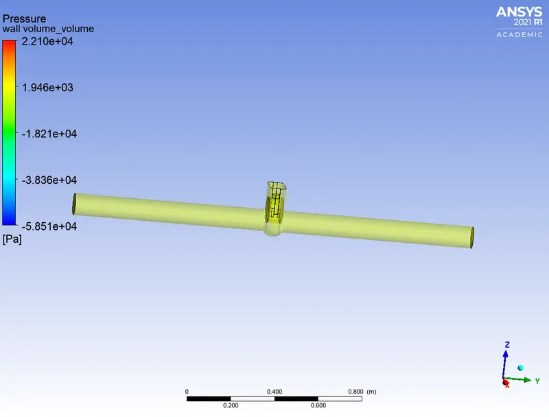
PRESSURE:
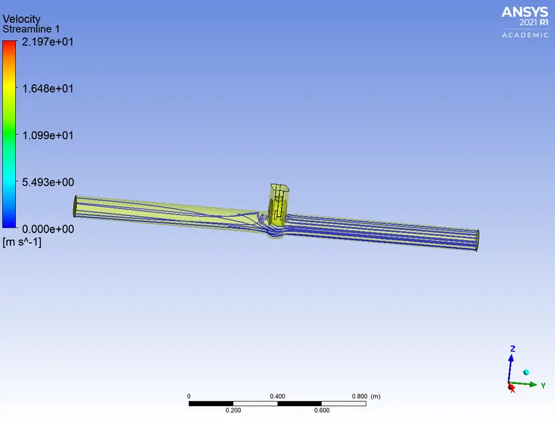
STREAMLINES:
CASE 5: 50mm
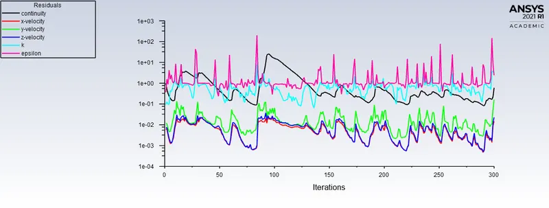
SCALE RESIDUAL:
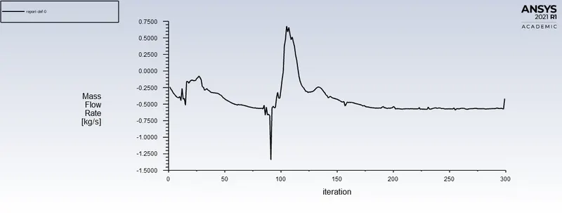
MASS FLOW RATE:
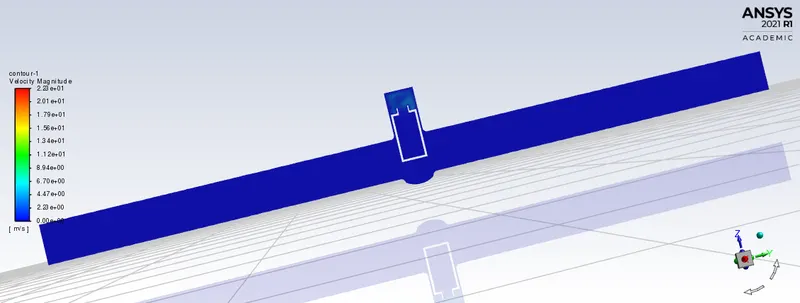
CONTOUR:
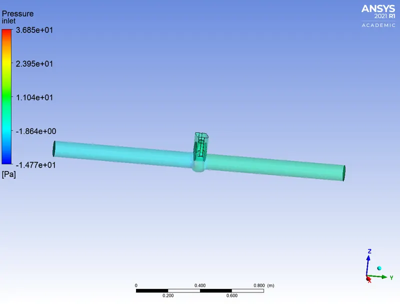
PRESSURE:
STREAMLINES:
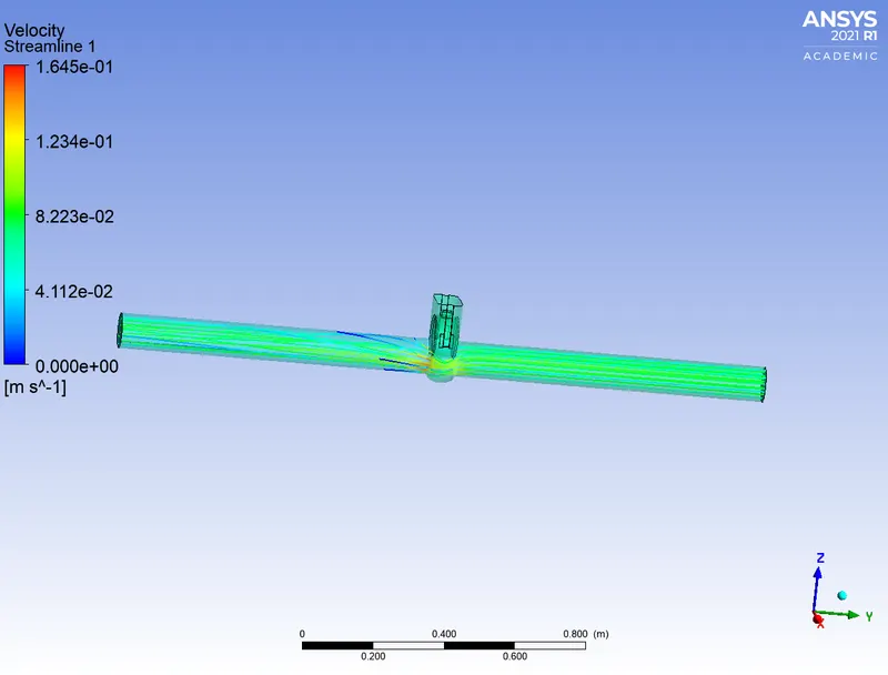
CASE 6: 60mm
SCALE RESIDUAL:
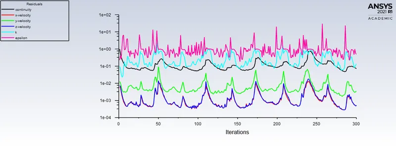
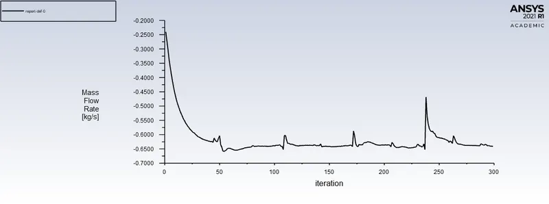
MASS FLOW RATE:
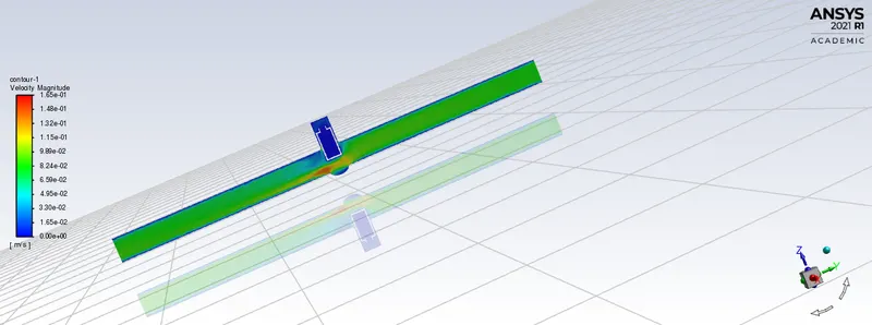
CONTOUR:
PRESSURE:
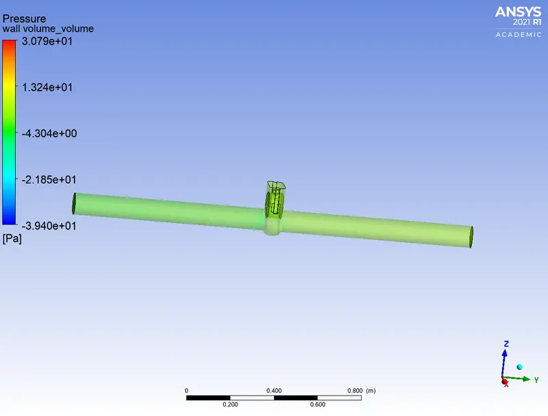
STREAMLINES:
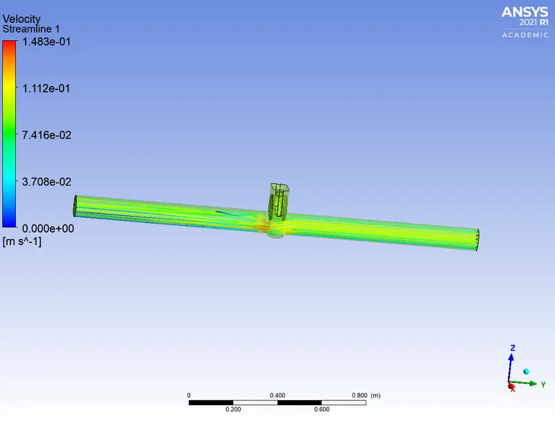
CASE 7: 70mm
SCALE RESIDUAL:
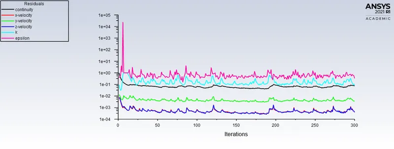
MASS FLOW RATE:
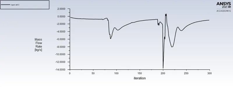
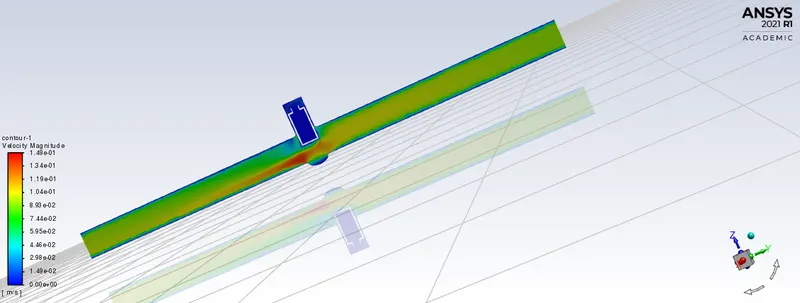
CONTOUR:
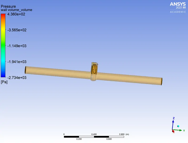
PRESSURE:
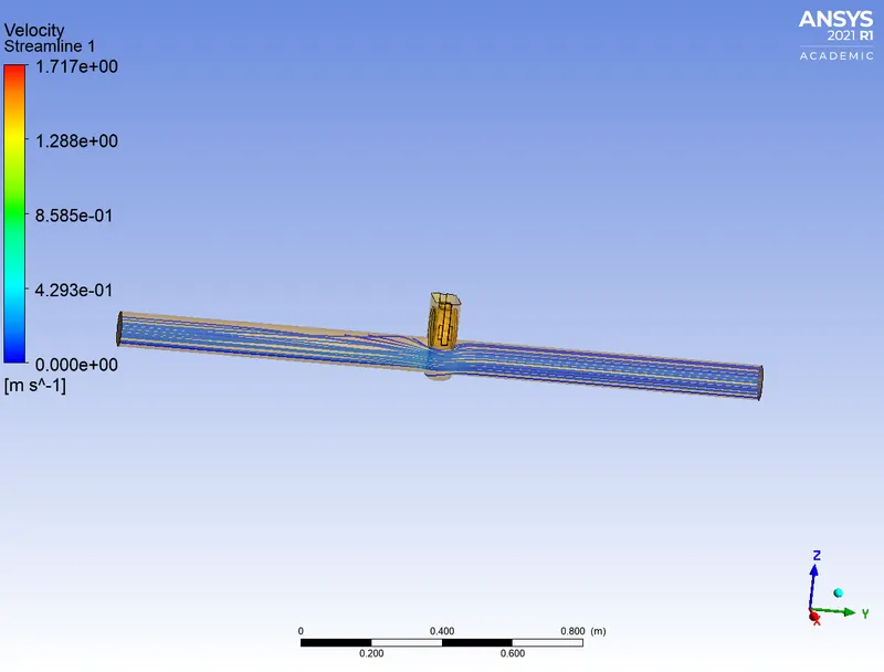
STREAMLINES:
CASE 8: 80mm
SCALE RESIDUAL:

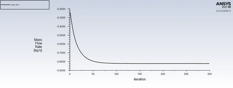
MASS FLOW RATE:
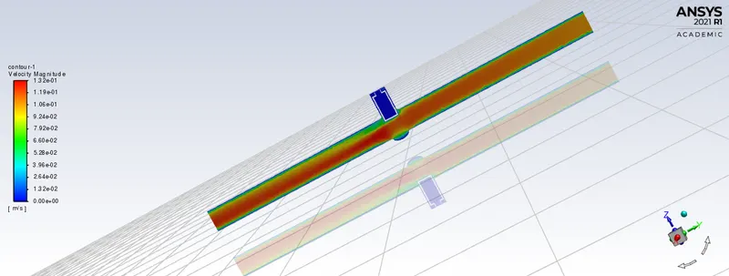
CONTOUR:
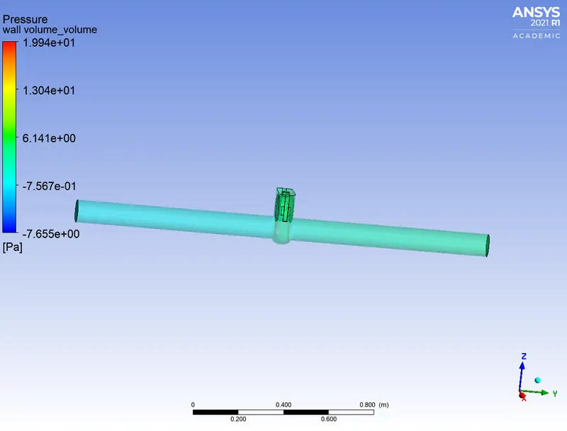
PRESSURE:
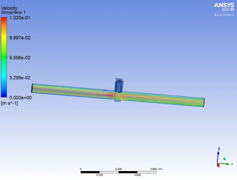
STREAMLINES:
RESULT:
FLOW FACTOR:
To calculate the Kv factor for liquids, the flow rate in l/min or m3/h, the density of the medium upstream of the valve and the pressure drop across the valve must be known, i.e. the difference between input pressure and back pressure.
Kv= 0.865*Cv
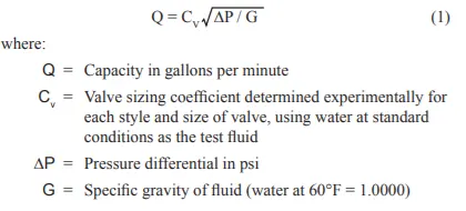
FLOW COEFFICIENT:
The volume flow rate for liquids can be calculated by multiplying the fluid velocity times the flow area. Thus, Cv is numerically equal to the number of U.S. gallons of water at 60°F that will flow through the valve in one minute when the pressure differential across the valve is one pound per square inch.
| S.No | GATE DISC LIFT | MASS FLOW RATE | PRESSURE DROP | FLOW COEFFICIENT | FLOW FACTOR (Fv) |
| 1 | 10 | 0.2365 | 9.50125 | 0.074787686 | 0.064691348 |
| 2 | 20 | 0.36049 | 8.9042 | 0.113996671 | 0.098607121 |
| 3 | 30 | 0.46767 | 8.1542 | 0.147889881 | 0.127924747 |
| 4 | 40 | 0.61754 | 7.3485 | 0.195282822 | 0.168919641 |
| 5 | 50 | 0.64096 | 6.5146 | 0.202688858 | 0.175325862 |
| 6 | 60 | 0.71674 | 6.1252 | 0.22665254 | 0.196054447 |
| 7 | 70 | 0.75031 | 5.7515 | 0.23726828 | 0.205237063 |
| 8 | 80 | 0.8224 | 4.8648 | 0.260065085 | 0.224956298 |
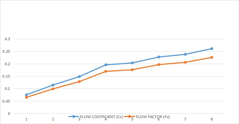
OBSERAVTION (from the graph):
- As the opening of the gate valve disc increases, Mass flow rate increses also the flow factor.
- Incraese in the Mass flow rate, there is an increment in the flow coefficient.
- we could see the linearity in the graph of Mass flow rate, Flow coefficient, Flow factor against the gate disc lift.
CONCLUSION:
- we can conclude from the above results that velocity in the first case is very low. As the lift increses the velocity also increases.
- As there is no any restriction at the flow, pressure become zero.It means there is minimal poressure drop.
- The maximum value of Mass flow rate, Flow coefficient, Flow factor is obtained at disc lift fully raised.
- The parametric study also help to solve and analyse the different position of valve lift.