Week - 9 Material Modeling from Raw Data
AIM: To create the curve form the give n MATERIAL CURVE IMAGE and then use the required material to create the MODEL.
PROCEDURE:
- Now first we we have the the MATERIAL CURVE IMAGE from that we have to create curve.
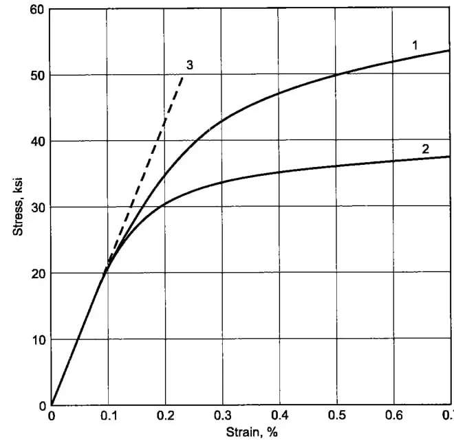
- Now with the help of DIGITALIZER we have created the curve.
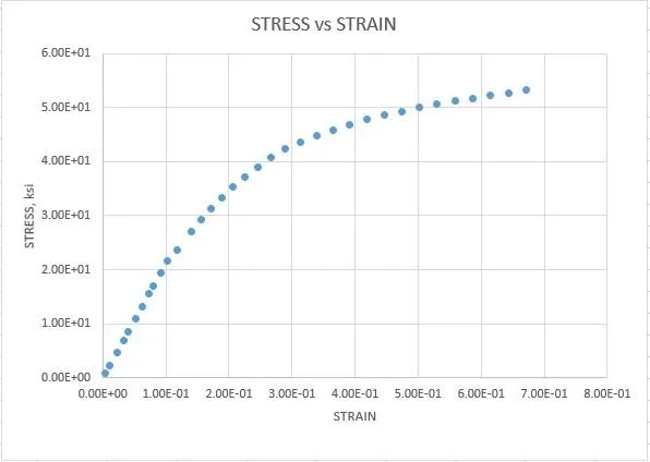
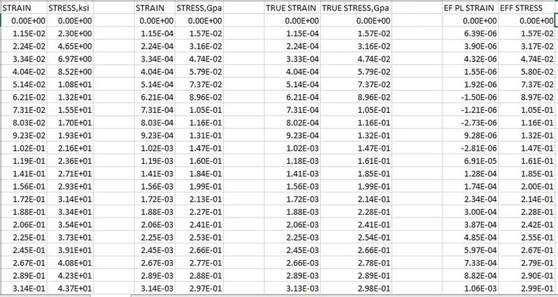
- The strain value is in % then the graph of strain value without % is shown below:
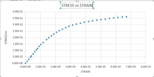
- Now we have to convert the the ENGINEERING STRAIN adn ENGINEERING STRAIN to TRUE STRESS AND TRUE STRAIN
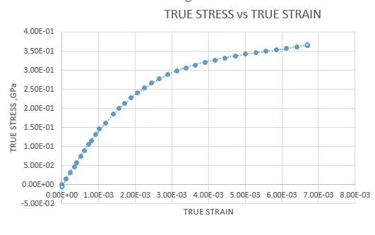
- TRUE STRAIN= `ln(1+epsilon)`
- TRUE STRESS= `sigma*(1+epsilon)`
- EFFECTIVE PLASTIC STRAIN = TRUES STRESS - TRUE STRAIN/E
- A graph for TRUE STRESS vs TRUE STRAIN is plotted below:
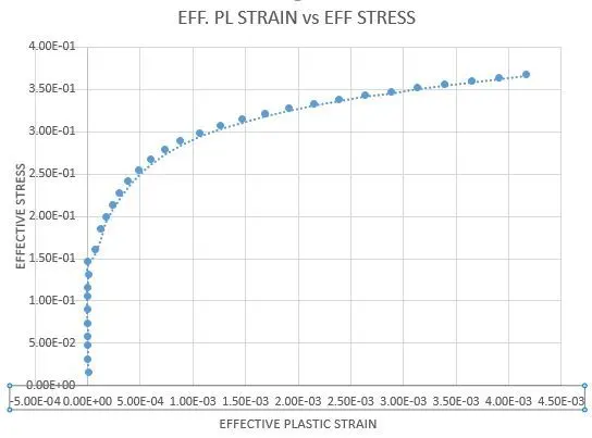
- Now we have to convert the TRUE STRAIN into EFFECTIVE PlASSTIC STRAIN. and TRUE STRESS into EFFECTIVE STRESS
- Now we are using E=144
- So the graph is look like this:
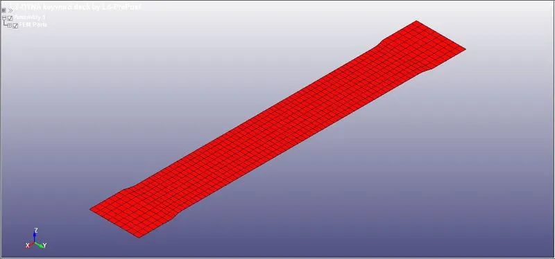
- Now we will open the .k file and assign the proeperty and the curve points.
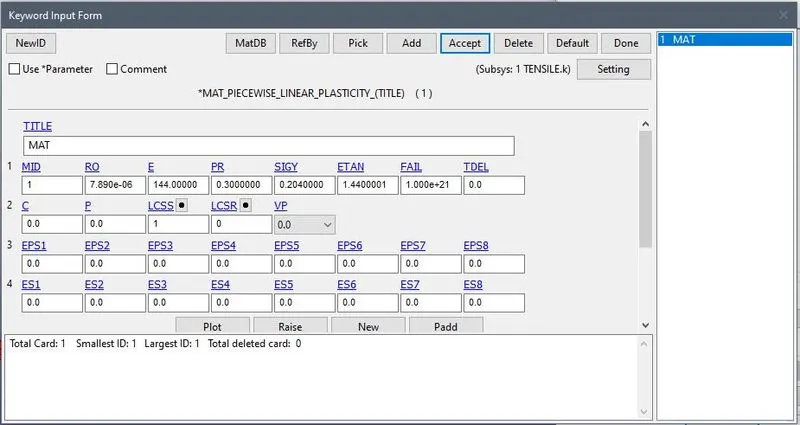
- Now we will define the material property for the model.
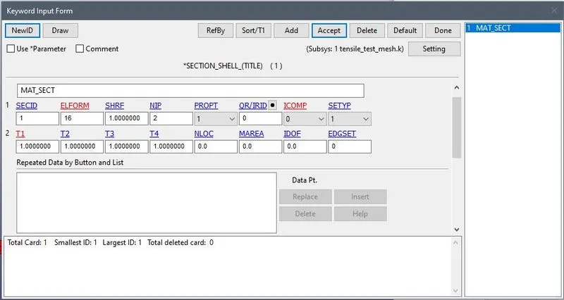
- Now we will create a section for the model. and then assign to the part.
- Now we will define the curve we created using the Material curve image.
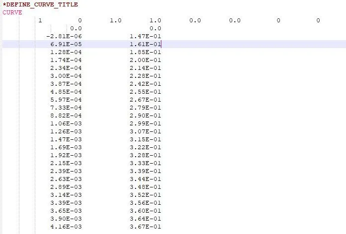
- Now we will give boundry condition to the mode.
- We will restrained all the dof of one side except Y direction.
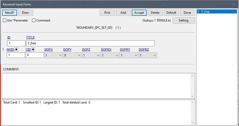
- Now next we will select one point from both side to and restrict the Y dierection only.
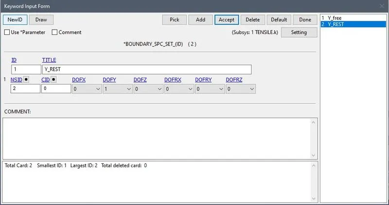
- Now we will for PRESCRIBED MOTION we will select another side.
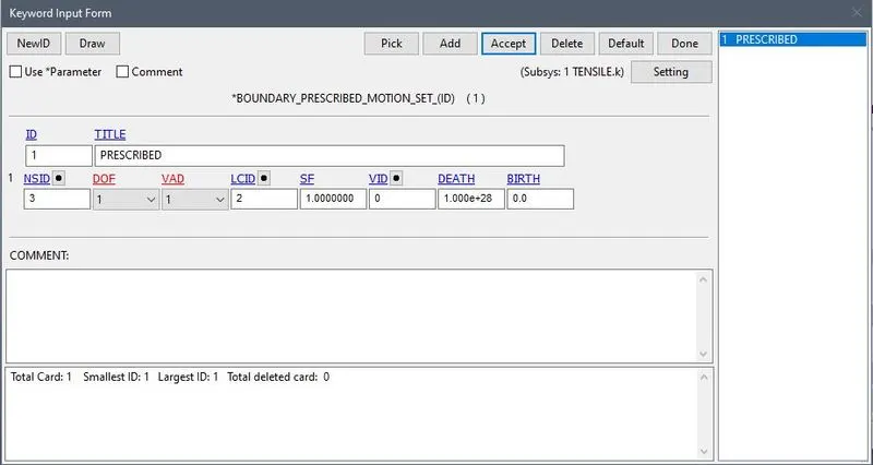
CHART
Control cards:
*CONTROL_IMPLICIT_GENERAL:
It activates Implicit analysis and defines associated control parameters. This keyword is required for all implicit analysis
- IMFLAG - Implicit/Explicit analysis type flag: 1- Implicit analysis.
- DT0 – Initial time step size for implicit analysis:0.01
- IMFORM - Element formulation flag for seamless spring back: 2 retain original element. formulation (default).
*CONTROL_IMPLICIT_AUTO
This card has been defined to adjusts the time step size automatically.
- IAUTOset to 1 which automatically adjusts the timestep size.
- ITEOPToptimizes the operation count step:60
- ITEWINis the iteration window:5
Database Creation: *BINARY_D3PLOT ,*DATABASE_HISTORY_NODE , *DATABASE_EXTEND_BINARY, this writes the strain tensor to d3plot when STRFLG is set to 1.
ASCII_option keyword:
RESULTS:
EFFECTIVE PLASTIC STRAIN
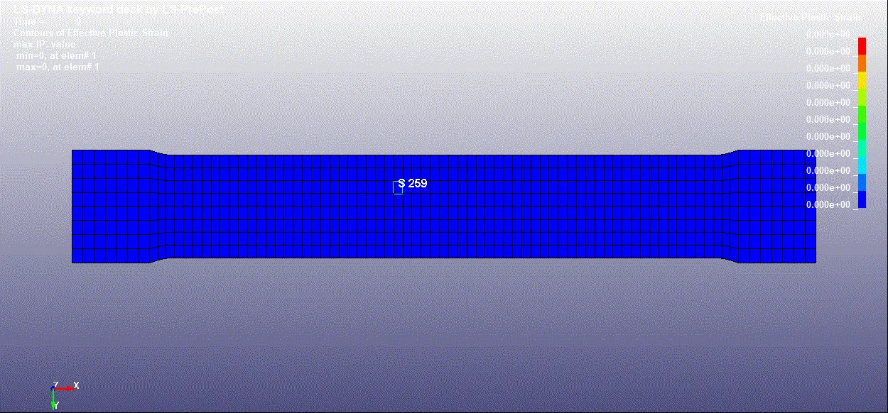
As per the defined displacment, the maximum value of effective plastic strain obtained is 0.0056. The strain propagation is starting the reduction in cross section region and propagating further towards the centre.
GRAPHS:
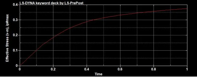
EFFECTIVE STRESS:
EFFECTIVE STRAIN:
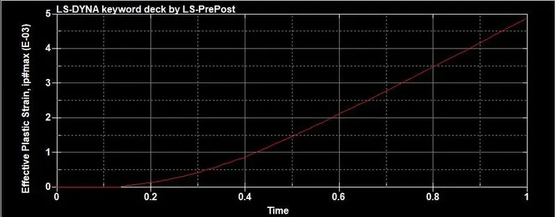
From the two plots, it can be inferred that the same behaviour is obtained as given by the contour. The element is in the middle portion of the specimen.
CONCLUSION:
- Material modeling a very important step in a CAE Analysis, this needs to be done in a careful way because wrong material data will hamper your Results.
- Depending upon the type of data either engineering or true we need to convert them into tool compatible.
- From the stress-strain plot, we can say(visually) that 1.44 Gpa is the yield point from where the non-linear behavior starts.
- As a result, the simulated curve from LS-post fits the extracted data which validates the material model which is well satisfied.