Week 9 Machining with Planer Challenge
Machining-Planar
Aim
To model a simple machining model system and determine strains and stresses.
Procedure
- Start a new explicit dynamics model in ansys and import the model
- Add the materials as shown.
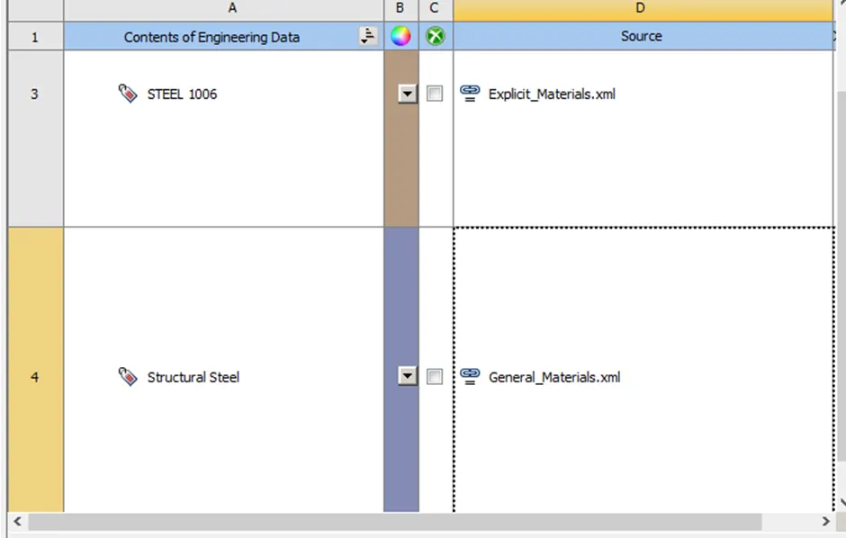
- Open this model in ansys mechanical.
- Assign Steel-1006 to the workpiece
- Delete the contacts and leave body interactions as is.
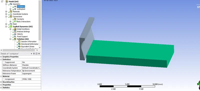
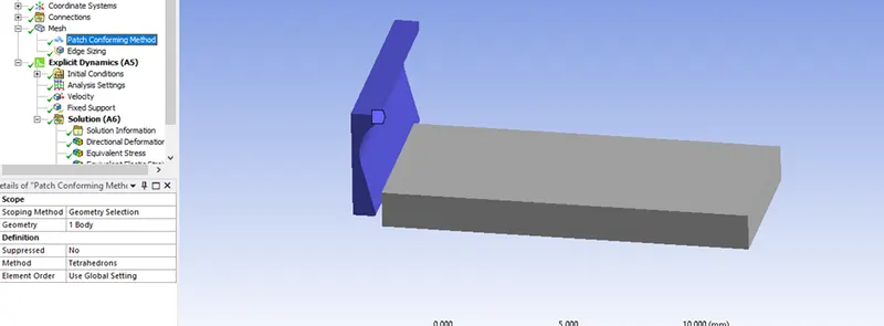
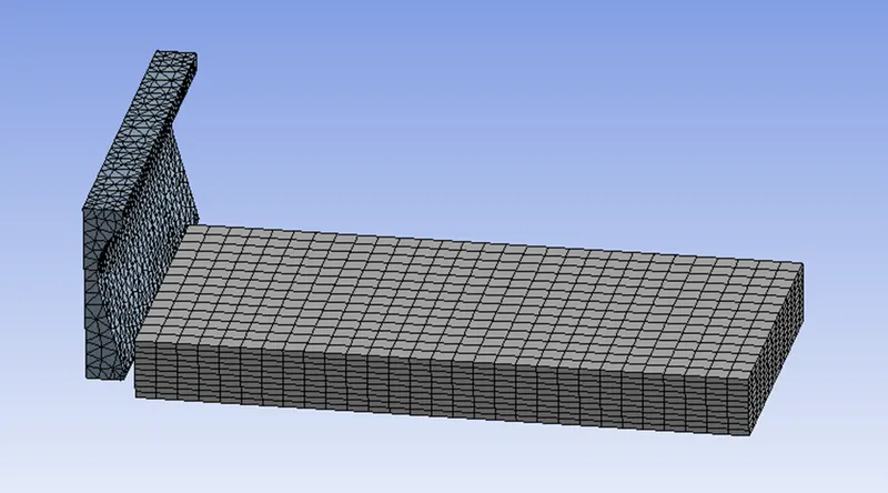
- Create type of mesh and set the machining tool to complete tetrahedron elements.
- For the workpiece, create 10divisions of hexa elements using face sizing tool
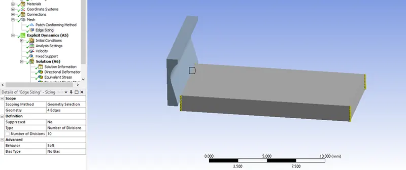
- Generate the mesh.
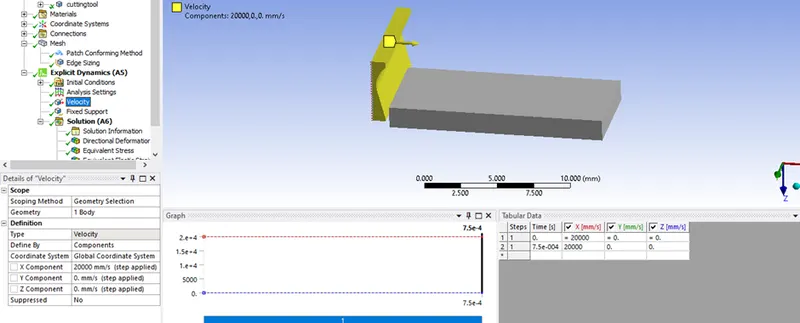
- Define the velocity along X axis for the tool and set y/z to 0.
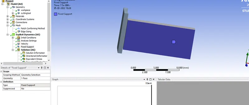
- Define fixed support for the workpiece.
Analysis Settings
Set the analysis settings as shown.
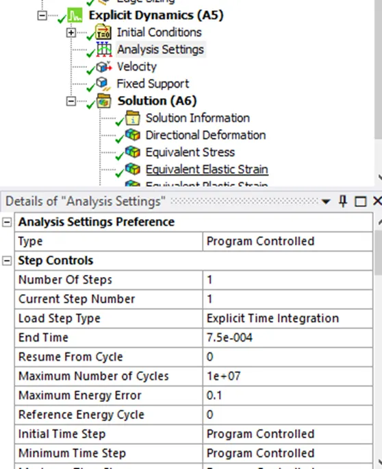
(set energy error to 0.2 in second case if you get energy error from solver)
Set your output blocks as shown
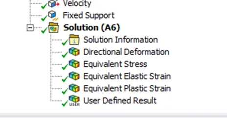
Plastic strain:select only the body
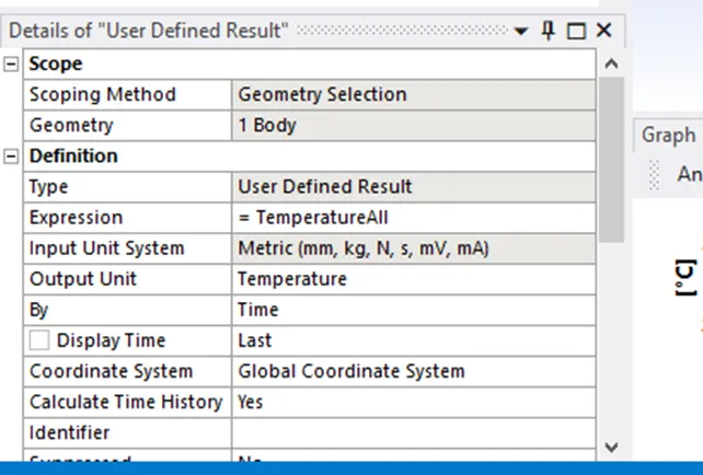
Userdefined Result:
Post Processing
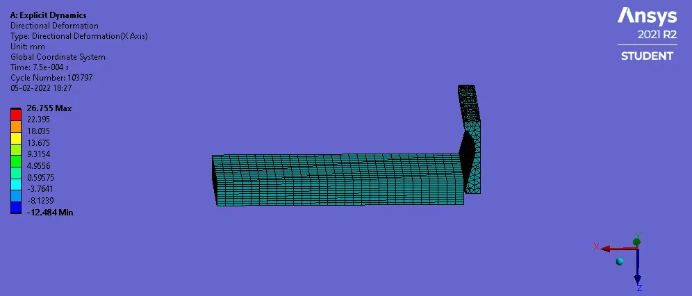
Case 1:
Velocity: 20000mm/s
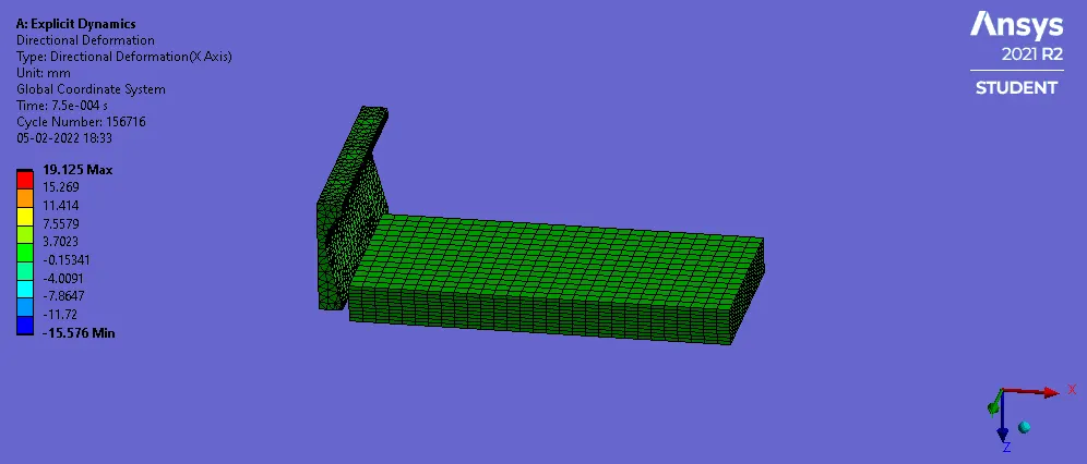
Case 2:
Velocity:15000mm/s
Tabulated Results
|
Case |
Case 1 |
Case 2 |
|
Maximum Stress (MPa) |
674 |
674.45 |
|
Maximum Deformation (mm) |
26.755 |
19.125 |
|
Elastic Strain |
0.0032532 |
0.0032442 |
|
Plastic Strain (workpiece) |
1.4959 |
1.4953 |
|
Temperature(C) |
367.77 |
364.74 |
It can be seen that the stresses and deformation are higher for case one compared to case 2.
This is due to the lower velocity and the fact that the complete component has not been machined in case 2.
The time should be increased for more accurate results in the case of 15000mm/s.
Conclusion
In this project, a simple workpiece machining setup was modelled and run to determine the differences in stresses and deformation experienced in 2 different cases.