Week 9 Machining with Planer Challenge
AIM: The main aim of this week challenge is to perform a explicit dynamic simulation of planar machining. The analysis is performed for two cases with different cutting velocity of the tool over the workpeice.Then compare the results of the stress,strain and deformation plots with a detailed explanation for the plots.
PROCEDURE:
CASE: 1
step 1: Open the ansys workbench module and select the transient structural analysis.
step 2: Now open the engineering data and add Steel 1006 in the explicit materials section.
step 3: Right click the geomentry tab and select import geomentry --> browse --> select the file --> open.
step 4: Now open the geomentry in mechanical modeller.
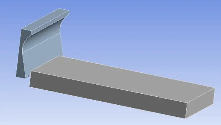
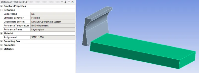
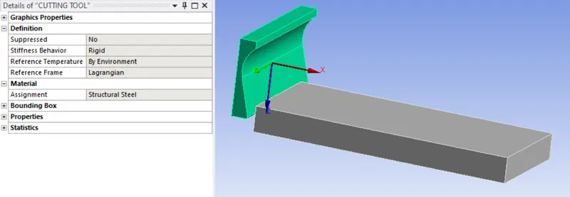
step 5: Now assign the material for both workpiece and tool.
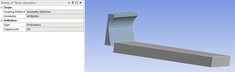
step 6: Now create a body interaction between the workpiece and tool.
step 7: Now add a meshing method for the workpiece and mesh the model.
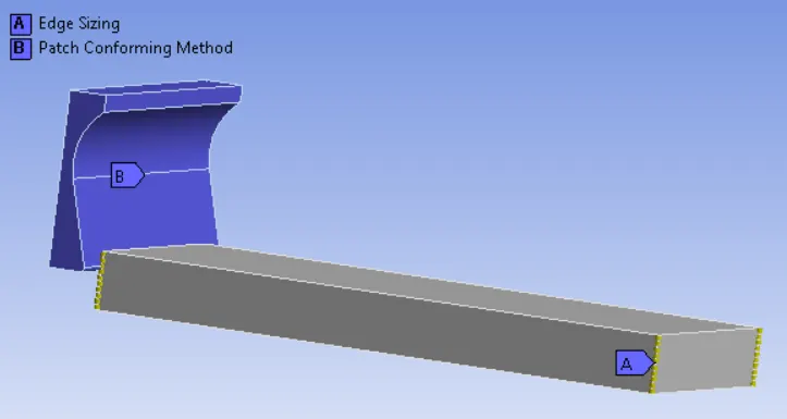
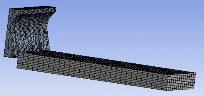
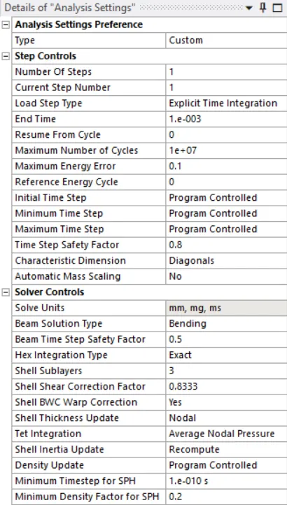
step 8: Now cange the analysis settings.
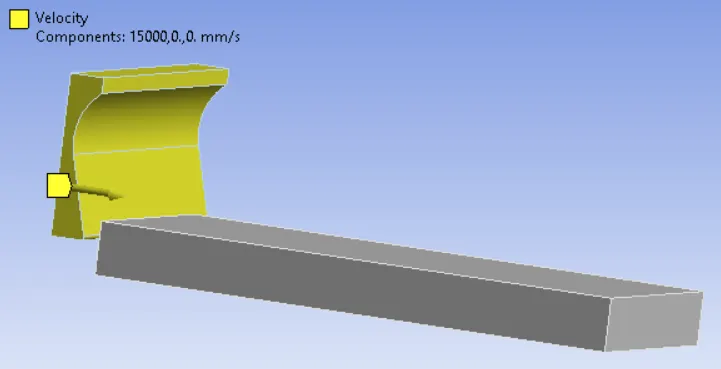
step 9: Now assign the velocity to the tool and fixed support to the workpiece.
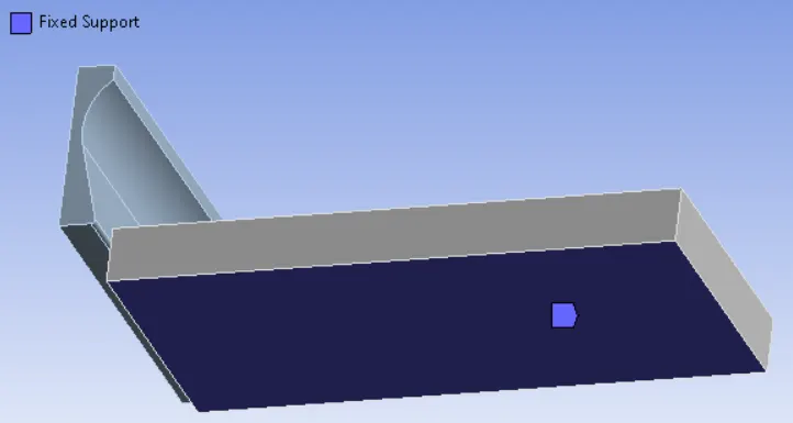
step 10: Now run the simulation.
step 11: Now include the total deformation,Equivalent stress and strain in output files.
step 12: Now change the model as per the question and run the simulation
Step 13: Compare the result plot and give a detailed explanation.
CASE: 2
step 1: Open the ansys workbench module and select the transient structural analysis.
step 2: Now open the engineering data and add Steel 1006 in the explicit materials section.
step 3: Right click the geomentry tab and select import geomentry --> browse --> select the file --> open.
step 4: Now open the geomentry in mechanical modeller.
step 5: Now assign the material for both workpiece and tool.
step 6: Now create a body interaction between the workpiece and tool.
step 7: Now add a meshing method for the workpiece and mesh the model.
step 8: Now cange the analysis settings.
step 9: Now assign the velocity to the tool and fixed support to the workpiece.
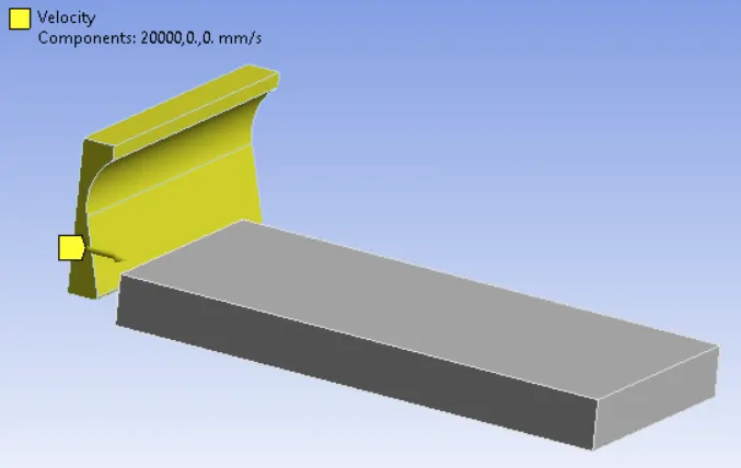
step 10: Now run the simulation.
step 11: Now include the total deformation,Equivalent stress and strain in output files.
step 12: Now change the model as per the question and run the simulation
Step 13: Compare the result plot and give a detailed explanation.
OUTPUT REQUEST:
CASE 1:
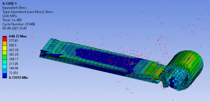
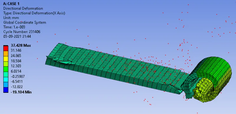
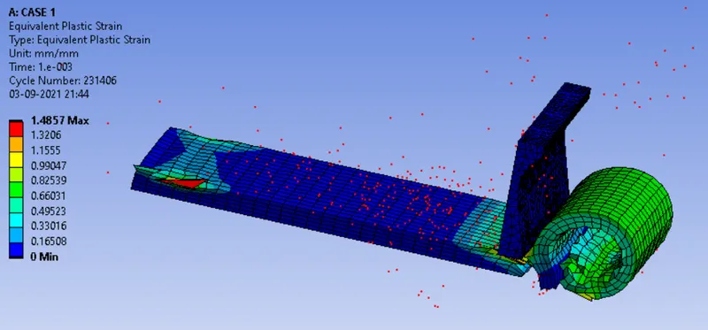
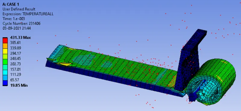
CASE: 2
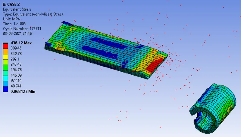
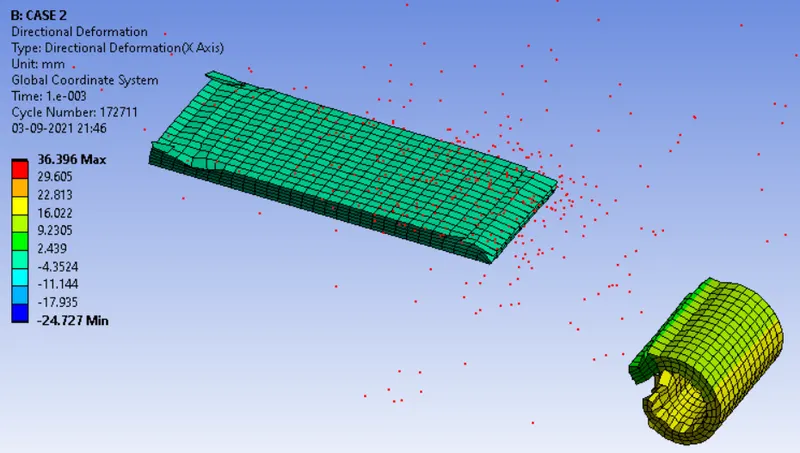
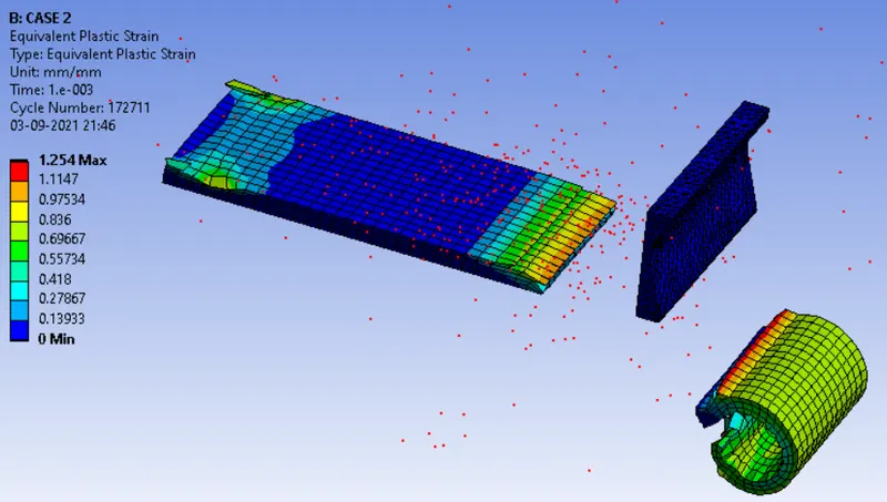
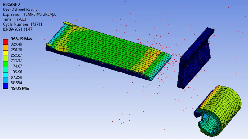
CONCLUSION:
| EQUIVALENT STRESS | DEFORMATION | PLASTIC STRAIN | TEMPERATURE | |
| CASE 1 | 649.72 | 37.42 | 1.485 | 431.22 |
| CASE 2 | 438.12 | 36.39 | 1.254 | 368.19 |
Based on the above result we can infer that the equivalent stress is much higher in case 1 than in case 2.The maximum deformation is almost the same for both the cases and the temperature is higher in case 1 than in case 2. The plastic strain is also almost similar for both the cases.