Week 9 Machining with Planer Challenge
Case Study of Workpiece Cut by a tool in Explicit Dynamic.
Objective:
You will have to perform an explicit dynamics simulation to find out the Equivalent Stress, Total Deformation and also insert a User defined result to calculate the temperature of the body. You need to perform this for 2 cases. One will be with a cutting velocity of 20000mm/s and the other will be with a cutting velocity of 15000mm/s.
Procedure:
Case1:
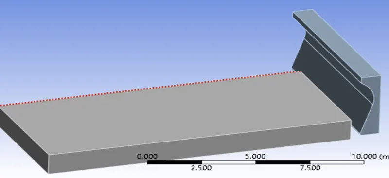
For Case 1, Static Structural Analysis is carried out on Workpiece. The material is Steel 1006 and the analysis is carried out on Ansys Workbench. The geometry of the model is imported on the Ansys Workbench for analysis. The Analysis system taken is Explicit Dynamic.
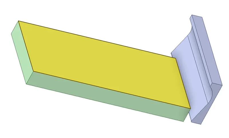
2D Geometry is extruded in the Space Claim to get the model to be imported to the ANSYS. The Extruded model is as shown in the image below:
The properties of the material is stated below:
|
Density |
|
Thermal
|
Specific Heat Constant Pressure |
|
Other
|
Gruneisen Coefficient |
|
||
|
Initial Yield Stress |
|
||
|
Hardening Constant |
|
||
|
Hardening Exponent |
|
||
|
Strain Rate Constant |
|
||
|
Melting Temperature |
|
||
|
Shear Modulus |
|
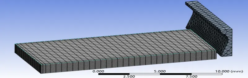
The model is meshed using Ansys Mesher with an element size of 1.5 mm, and a patch conforming method using tetrahedrons was employed. This is done to get the best refinement within the limitation of Ansys Academic License.
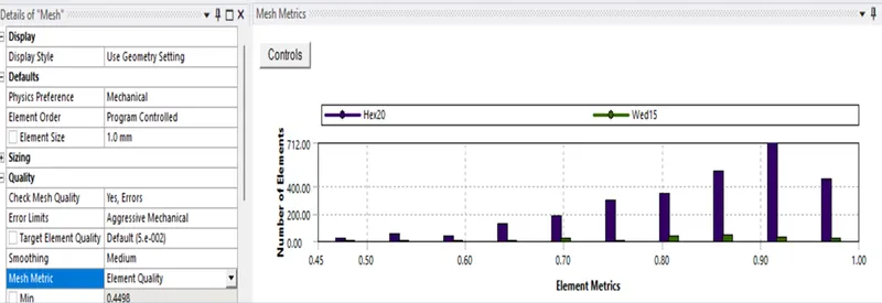
A mesh metric that identifies the elements according to their quality was employed and it can be seen that element of lowest quality are minimal. Most of the elements have very high quality in the range of 0.7-1. Hence, the mesh is of acceptable quality. The meshed model is shown in image below:
The Workpiece is fixed at one end and the cutting tool is dragged at a velocity of 20000 mm/s from the other end, simulation is then run with the setting and the results are then obtained.
Case 2:
The Workpiece is fixed at one end and the cutting tool is dragged at a velocity of 15000 mm/s from the other end, simulation is then run with the setting and the results are then obtained.
Results:
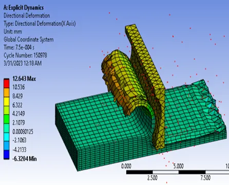
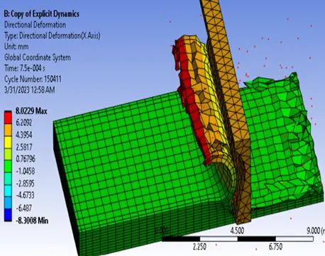
Total Directional deformation of the 2 cases are compared.
Time [s] Minimum [mm] Maximum [mm] Average [mm]
7.5e-004 -6.3204 12.643 1.6086
7.5e-004 -8.3008 8.0229 1.0403
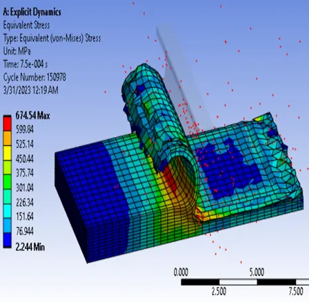
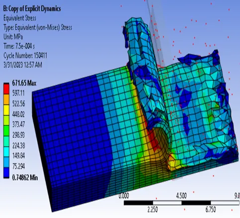
Equivalent Stress of the 2 cases are compared.
Time [s] Minimum [Mpa] Maximum [Mpa] Average [Mpa]
7.5e-004 2.244 674.54 160.77
7.5e-004 0.74862 671.65 141.97
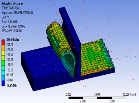
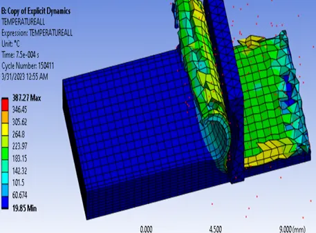
Temperature of the 2 cases are compared.
Time [s] Minimum [mm/s] Maximum [mm/s] Average [mm/s]
7.5e-004 19.85 346.03 65.4
7.5e-004 19.85 387.27 54.806
The total directinal deformation on the gear is as plotted and is shown on the plate below.
The Equivalent stress is plotted on the plate and is as shown below
The Temperature is plotted on the plate and is as shown below
Conclusion:
The average deformation, equivalent stress and temperature is more in case 1 than that of the case 2. Therefore, Case 2 is preferrable from the analysis point of view.