Week 9 Machining with Planer Challenge
Machining with Planer
Aim:
To perform an Explicit Dynamics analysis of the mechanism "machining with planar" for two different velocity cases of the tool.
Geometry:
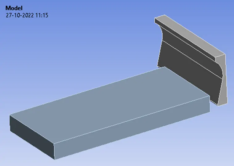
The 3D assembly model of the machining with planar mechanism is shown in the figure below:
Material Properties:
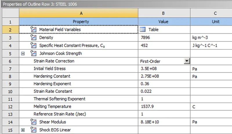
The material of the workpiece is set to be Steel 1006 and that of the Cutting tool is set to be Structural Steel for both cases. The material properties are given below:
Connection Details:
The default contact identified by the workbench is deleted as the interaction between the workpiece and the cutting tool is not a major concern for this study. Also, the body interactions are set to be frictionless.
Meshing:
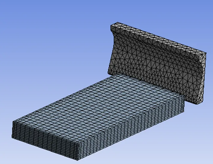
An edge sizing of 10 divisions was allocated to the four corners of the workpiece thus leading to the formation of uniform elements for the rectangular workpiece. For the Cutting Tool, a patch-confirming technique is provided with the element method of Tetrahedrons due to its complicated shape. The total number of nodes and elements generated are 7700 and 8308 respectively. The generated mesh can be seen below:
Boundary Conditions:
For analysis settings, the end time is given as 0.00075 s with the initial, maximum, and minimum time to be as program-controlled.
For this analysis the number of steps is set to 1 with a maximum number of cycles is 1e+07 and the end time is 7.5e-4 and it is defined by time, hence initial, maximum and minimum time will be program-controlled. The maximum energy error was set to 2.
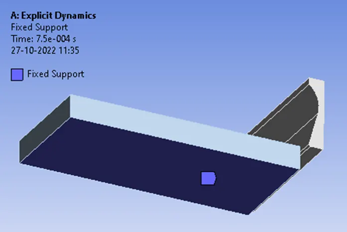
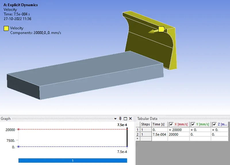
In order to simulate the motion, the workpiece was fixed on its bottom surface and the Cutting tool was made to move along the x-axis with appropriate velocity for each case.
Fixed Support to the Workpiece
Velocity for the Cutting Tool
For case 1, the velocity was set to be 20,000 mm/s and for case 2 with the cutting tool velocity of 15,000 mm/s was set.
Simulation Results:
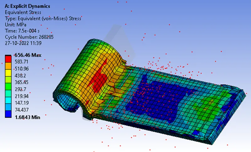
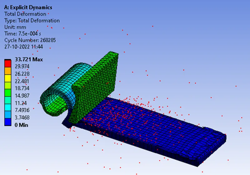
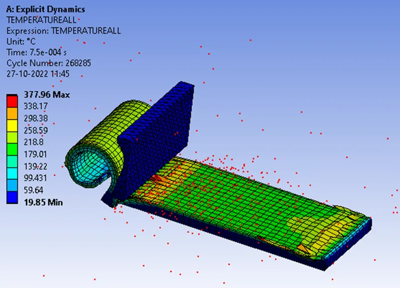
Below provides the observation for case 1 where the velocity of the cutting tool is 20,000 mm/s.
Equivalent Stress:
Total Deformation
The user-defined result to calculate the temperature of the body
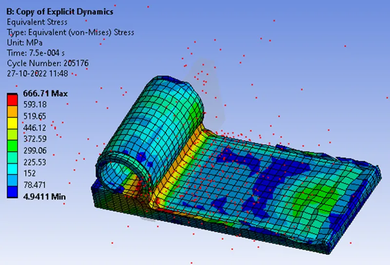
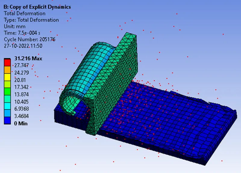
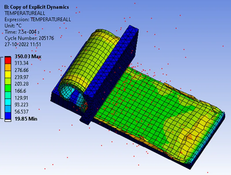
Case 2 with the cutting tool velocity of 15,000 mm/s
Equivalent Stress
Total Deformation
The user-defined result to calculate the temperature of the body
Concluding Results
|
Analysis of the cases of |
Total Deformation mm |
Equivalent stress MPa |
User-defined Temperature ℃ |
|
20000 mm/s |
33.721 |
656.46 |
377.96 |
|
15000 mm/s |
31.216 |
666.71 |
350.03 |
The comparison table above shows that the stress in Case 2 is greater when the velocity is 15000 mm/s. When the velocity is low, the material can withstand more load and the stress is larger. The stress developed is way higher than the ultimate breaking strength, which is why the cutting process takes place. However, the plastic strain and deformations are greater in Case 1, owing to the high velocity of up to 20000 mm/s. Also, the temperature in Case 1 is higher because the velocity in Case 1 is 20000 mm/s, so with the speed, the tool will face more material cutting in a shorter period of time, so the heating will be greater due to greater interaction between tool and workpiece, so the temperature will be higher in Case 1.