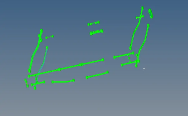
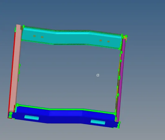
Week 9-Creation of 1D Connectors Challenge
AIM : To mesh the given geometry and create connectors and attach various parts using connectors.
GIVEN CRITERIA :
| S.NO | QUALITY CRITERIA | VALUE |
| 1 | ELEMENT SIZE | 5 UNITS |
| 2 | ASPECT RATIO | 5 UNITS |
| 3 | SKEW | 45 |
| 4 | MIN ELEMENT LENGTH | 2 |
| 5 | MAX ELEMENT LENGTH | 8 |
| 6 | MIN ANGLE QUAD | 135 |
| 7 | MAX ANGLE QUAD | 45 |
| 8 | MIN ANGLE TRIA | 110 |
| 9 | MAX ANGLE TRIA | 30 |
| 10 | TRIA PERCENTAGE | 15 |
| 11 | TAPER | 0.5 |
| 12 | WARPING | 15 |
| S.N0 | PARTS TO CONNECTED | CONNECTOR |
| A | RIGHT RAIL 2 AND FRONT TRUSS 1 | Seam-Quad(angled+capped+L) |
| B | LEFT RAIL2 AND FRONT TRUSS 1 | Quad elements |
| C | FRONT TRUSS 1 , FRONT TRUSS 2 AND RIGHT RAIL 1 | Spot weld with 2 Layers and 5 mm Diameter |
| D | FRONT TRUSS 1 , FRONT TRUSS 2 AND LEFT RAIL 1 | Hexa (Adhesive) |
| E | REAR TRUSS 2 AND RIGHT RAIL 2 | Bolt Connector |
| F | REAR TRUSS 2 AND LEFT RAIL 2 | Bolt Connector |
| G | RIGHT RAIL 1 AND RIGHT RAIL 2 | Spot-weld with Rigid Elements |
| H | LEFT RAIL 1 AND LEFT RAIL 2 | Spot-weld with Spring Elements |
Remaining parts all are to be joined with suitable conectors.
PROCEDURE :
STEP 1 : Insert model frame assemble file into hypermesh tool via optistruct profile .
STEP 2 : 1. As mid surace is already generated in question , direct mesh the components with element size 5 units in 2d automesh .
2. Remesh the elements at few places to obtain good mesh flow .
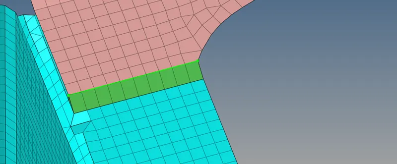
STEP 3 : A. RIGHT RAIL 2 AND FRONT TRUSS 1 with Seam quad (angled + capped +L)
1. Hide all components except right rail 2 and front truss 1 .
2. select connector from 1d panel and move to Seam quad (angled + capped +L) in seam panel .
3. select node list and components to connect and use remesh option .
4. Increase tolerance value to 10 and click create and remesh the area for better mesh flow.
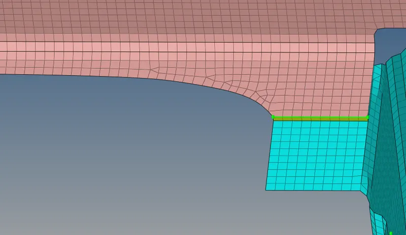
STEP 4 : B. LEFT RAIL2 AND FRONT TRUSS 1 with Quad elements
1. Hide all components except left rail 2 and front truss 1 .
2. 1d _connectors_ seam _quad type connector.
3. Select node list and components to connect and use remesh option .
4. Increase tolerance value to 10 and click create and remesh the area for better mesh flow .
STEP 5 : C. FRONT TRUSS 1 , FRONT TRUSS 2 AND RIGHT RAIL 1 with spot weld with 2 layers and 5mm diameter.
1. Hide all components except front truss 1 , front truss2 and right rail 1 .
2. 1D_CONNECTORS_SPOT_WELD diameter 5mm
3. select nodes and connectors to spot weld with 2 layers and diameter as 5mm.
4. Increase tolerance value and create property for spot weld and assign .
5. Clicl create and remesh the area for better mesh flow .
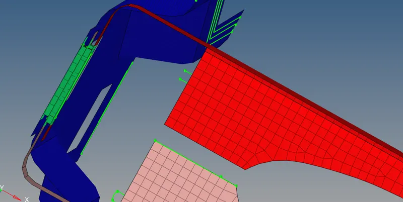
STEP 6 : D. Front truss 1 ,front truss2 and left rail1 with hexa adhesive
1. Hide all components except front truss1 , front truss 2 and left rail 1
2. 1D_CONNECTORS_SEAM _HEXA ADHESIVE
3. Select two components node list and connect to components initially, later select the other two components and connect
4. Increase tolerance value to 20 and click create and remesh the area for better mesh flow .
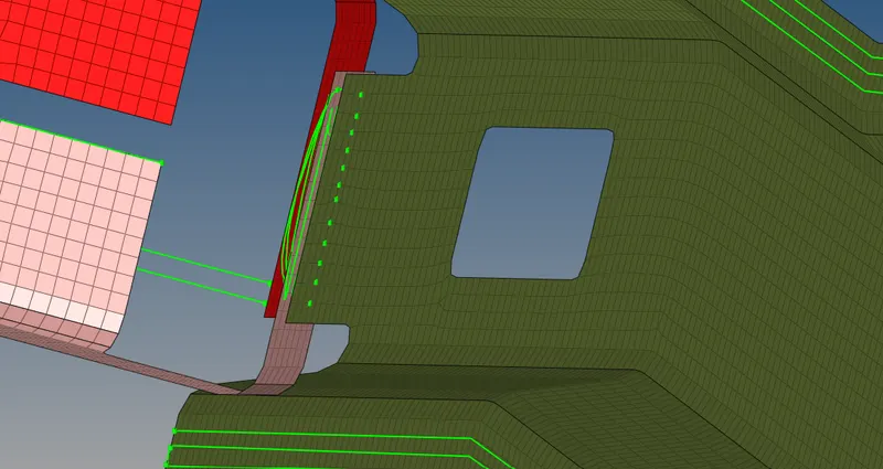
STEP 7 : E. Rear truss2 and right rail2 with bolt connector
1. Hide all components except rear truss2 and right rail 2
2. 1D_CONNECTORS_BOLT(GENERAL)
3. Select node list and components to connect
4. Increase tolerance value to 10 and create.
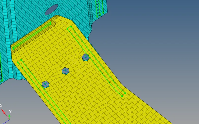
STEP 8 : F. Rear truss2 and left rail2 with bolt connector .
1. Hide all components except rear truss2 and left rail 2 .
2. 1D_CONNECTORS_BOLT(GENERAL)
3. Select node list and components to connect
4. Increase tolerance value to 10 and create.
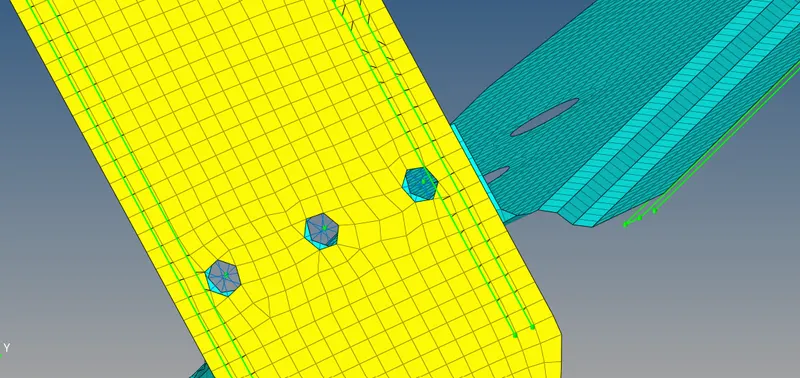
STEP 9 : G. RIGHT RAIL 1 AND RIGHT RAIL 2 with spot weld with rigid elements.
1. Hide all components except right rail 1 and right rail 2
2. 1D_CONNECTORS_SPOT _RIGID
3. Select the node list and components to be connected
4. Increase tolerance value to 10 and create .
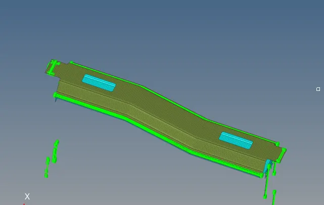
STEP 10 : G. LEFT RAIL 1 AND LEFT RAIL 2 with spot weld with spring elements.
1. Hide all components except left rail 1 and left rail 2
2. 1D_CONNECTORS_SPOT _SPRING
3. Select the node list and components to be connected
4. Increase tolerance value to 10 and create .
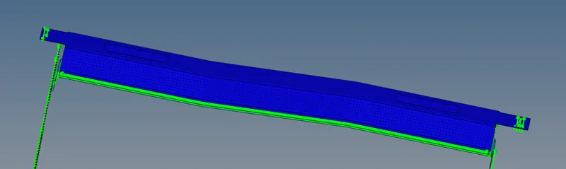
STEP 11 : Remaining all components are connected with various connectors .
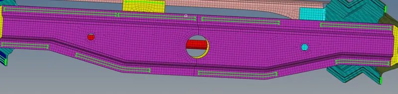
SPOT WELD WITH RIGID ELEMENTS
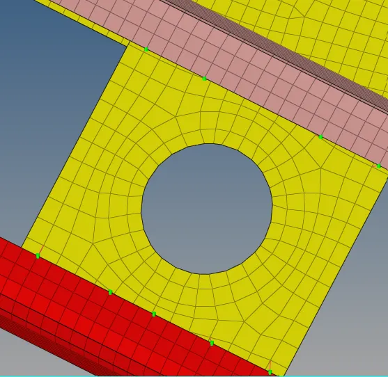
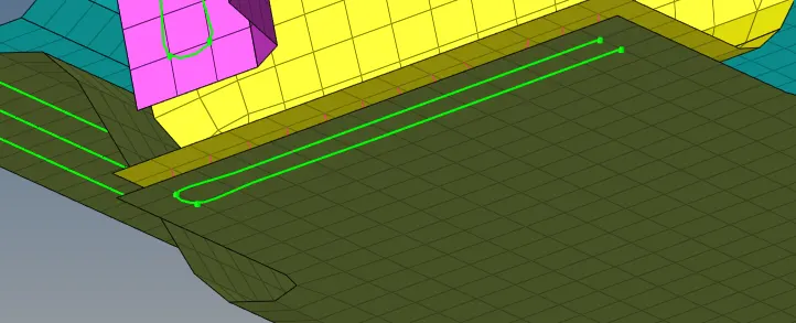
SPOT WELD SPOT WELD
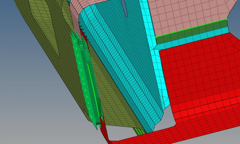
HEXA ADHESIVE
RESULTS AND FINAL MODEL IMAGE :
1 . Frame assembly is meshed properly
2. Components are connected with specified connectors and remaining components are connected with random connectors .