Creation of 1D Connectors in Hypermesh
Objective: To create 1D connectors on the frame assembly.
Procedure:
1. Import the assembly into hypermesh.
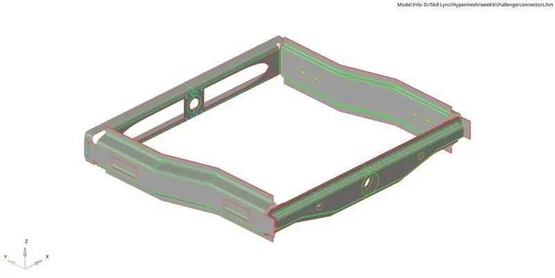
Fig 1: Imported assembly.
2. The frame assembly consists of the front truss, rear truss, right rails, left rails, and reinforcement plate.
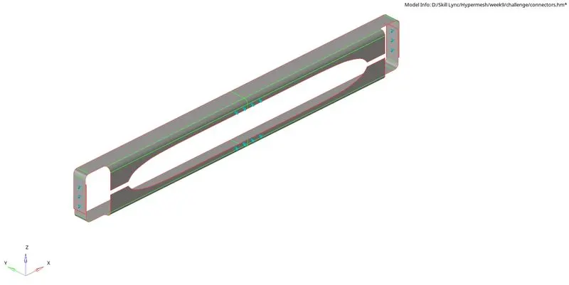
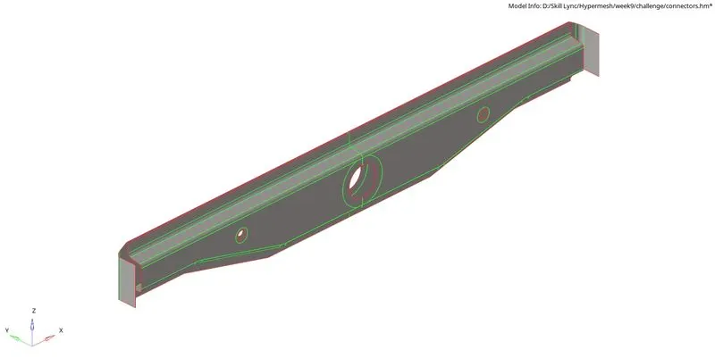
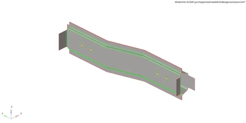
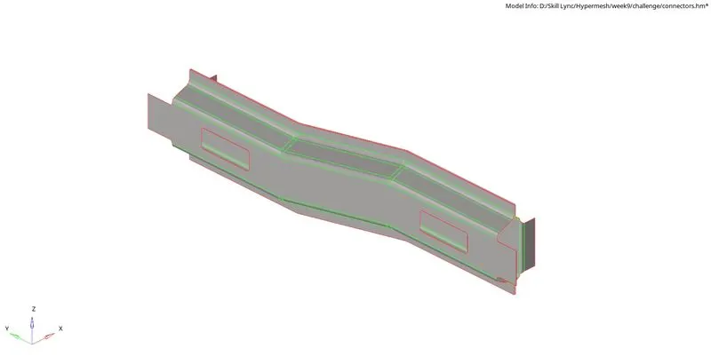
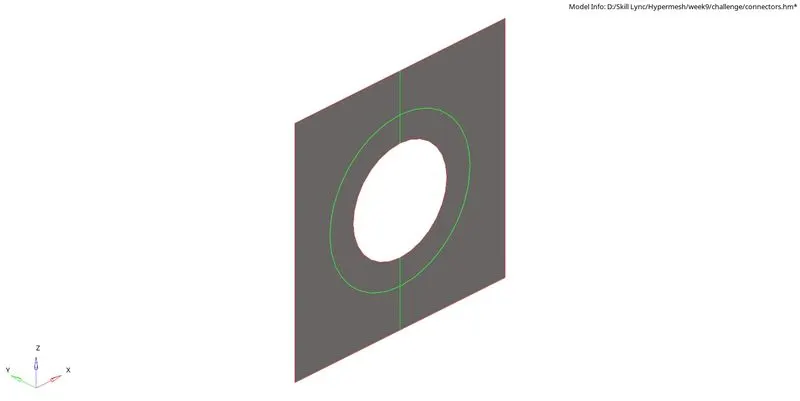
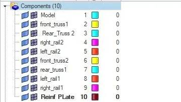
Fig 2: Components of the assembly.
3. Generate 2D mesh on the components with five units as the element length.
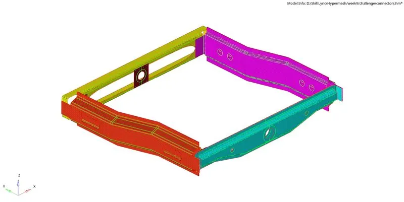
Fig 3: Generated mesh on the components.
4. The mesh is checked with the given criteria values:
|
S.N |
Quality Criteria |
Value |
|
1 |
Aspect Ratio |
5 |
|
2 |
Skewness |
45 |
|
3 |
Warping |
15 |
|
4 |
Taper |
0.5 |
|
5 |
Min. Length |
2 Units |
|
6 |
Max. Length |
8 Units |
|
7 |
Min angle Quad |
45 |
|
8 |
Max angle Quad |
135 |
|
9 |
Min angle Tria |
30 |
|
10 |
Max angle Tria |
110 |
|
10 |
Tria % |
15 |
If any element fails to satisfy the criteria, it is resolved by element cleanup tools and is rectified.
Creation of Connectors:
5. Hide all other components except for Right_Rail_2 & Front_truss_1. Navigate to connectors in the 1D tab, choose seam, and select the type as Seam-Quad(angled+capped+L). Select the nodes on the edge of one component where the connector should be placed, highlight the components to be connected and enter a search tolerance value of 30. Rest all settings can be changed as per our requirement.

Fig 4: Options for creating seam connector.
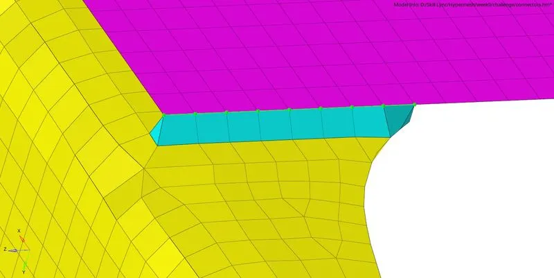
Fig 5: Seam-Quad(angled+capped+L) connector between Right_Rail_2 & Front_truss_1.
6. Hide all other components except for Left_Rail_2 & Front_truss_1. Navigate to connectors in the 1D tab, choose seam, and select the type as Quads. Select the nodes on the edge of one component where the connector should be placed, highlight the components to be connected and enter a search tolerance value of 30. Rest all settings can be changed as per our requirement.

Fig 6: Options for creating a quad connector.
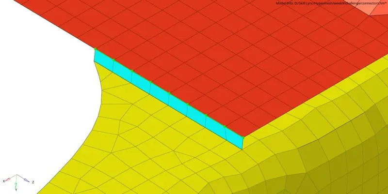
Fig 7: Quad connector between Left_Rail_2 & Front_truss_1.
7. Hide all other components except for Front_truss_2, Front_truss_1 & Right_Rail_1. Navigate to connectors in the 1D tab, choose the spot, and select the type as weld. Select the nodes on the edge of one component where the connector should be placed, highlight the components to be connected and enter a search tolerance value of 10—keeping the number of layers as two and a diameter of 5 units. Rest all settings can be changed as per our requirement.

Fig 8: Options for creating a weld connector.
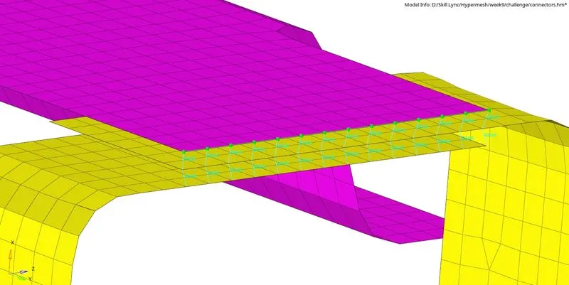
Fig 9: Weld connector between Front_truss_2, Front_truss_1 & Right_Rail_1.
8. Hide all other components except for Front_truss_2, Front_truss_1 & Left_Rail_1. Navigate to connectors in the 1D tab, choose the seam, and select the type as Hexa (Adhesive). Select the nodes on the edge of one component where the connector should be placed, highlight the components to be connected and enter a search tolerance value of 80—keeping the strips as one and coats as one. Rest all settings can be changed as per our requirement.

Fig 10: Options for creating an adhesive connector.
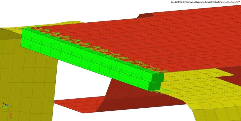
Fig 11: Hexa (Adhesive) connector between Front_truss_2, Front_truss_1 & Left_Rail_1.
9. Hide all other components except for Rear_truss_2 & Right_Rail_2. Navigate to connectors in the 1D tab, choose the bolt, and select the type as bolt (general). Select the location of the node of one component where the bolt should be placed, highlight the components to be connected and enter a search tolerance value of 20—keeping the number of layers as two. Rest all settings can be changed as per our requirement. The same process is repeated for Rear_truss_2 & Left_Rail_2 as well.

Fig 12: Options for creating a bolt connector.
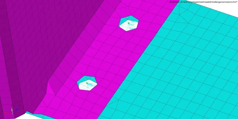
Fig 13: Bolt connector between Rear_truss_2 & Right_Rail_2.
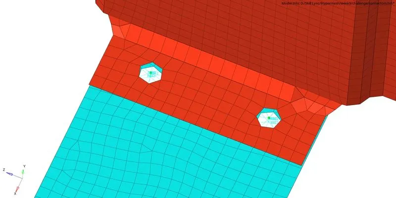
Fig 14: Bolt connector between Rear_truss_2 & Left_Rail_2.
10. Hide all other components except for Right_Rail_1 & Right_Rail_2. Navigate to connectors in the 1D tab, choose the spot, and select the type as rigid. Select the nodes on the edge of one component where the connector should be placed, highlight the components to be connected and enter a search tolerance value of 10—keeping the number of layers as two and a diameter of 5 units. Rest all settings can be changed as per our requirement. The same procedure is followed for Left_Rail_1 & Left_Rail_2 but with spring type of elements.

Fig 15: Options for creating a rigid connector.

Fig 16: Options for creating a spring connector.
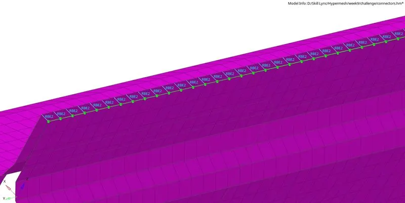
Fig 17: Rigid connector between Right_Rail_1 & Right_Rail_2.
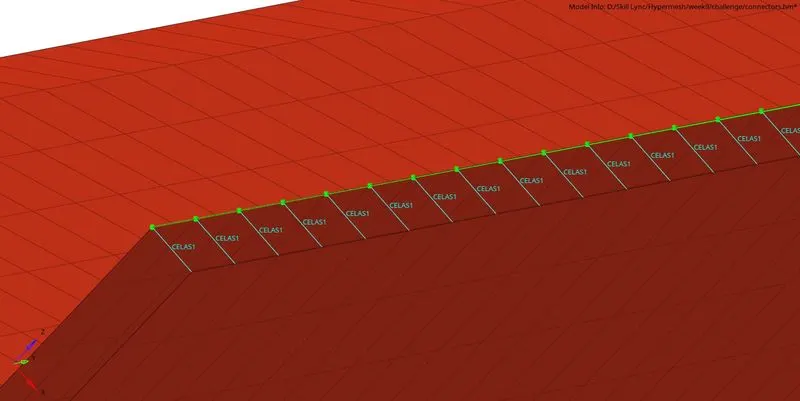
Fig 18: Weld connector between Left_Rail_1 & Left_Rail_2.
11. Remainings components are connected with either of the connectors as mentioned above.
12. Steel material is created with appropriate values to define it, and property is created with PSHELL and a thickness of 2 units.
Conclusion: The frame assembly is successfully joined with the mentioned connectors.
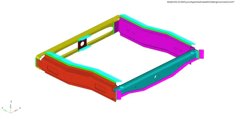
Fig 19: A 2D detailed representation of the component.