Meshing of Car Hood in Hypermesh
Objective: To generate 2D mesh on the hood geometry.
Procedure:
1. Import the given geometry file into hypermesh.
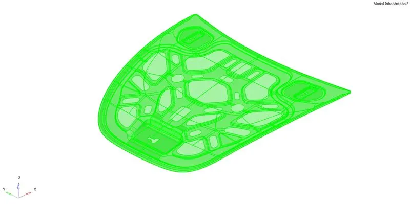
Fig 1: Imported geometry file.
2. The hood consists of four different components: outer extract, inner extract, latch reinforcement, and hinge reinforcement.
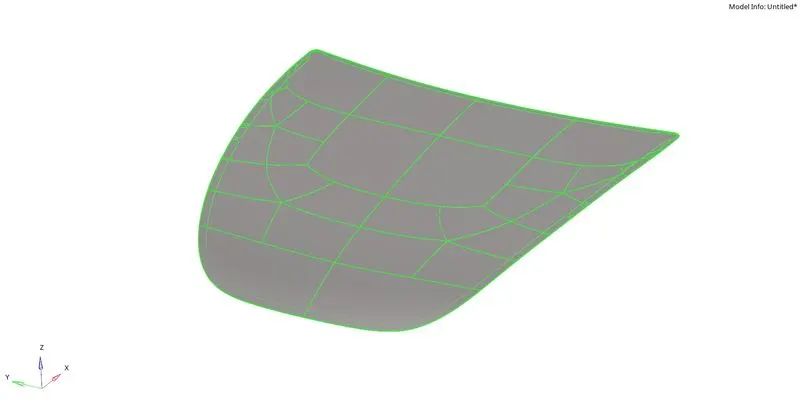
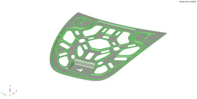
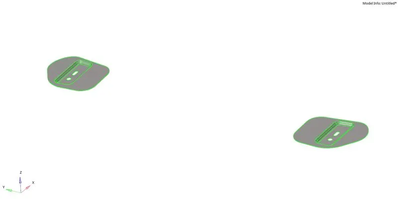
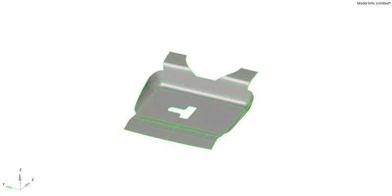
Fig 2: Different components of the hood.
3. Autocleanup is performed on each one of the components and to eliminate unwanted features from the geometry and to fix any surface errors in the geometry. Midsurface is extracted from each component and is assigned to new components.
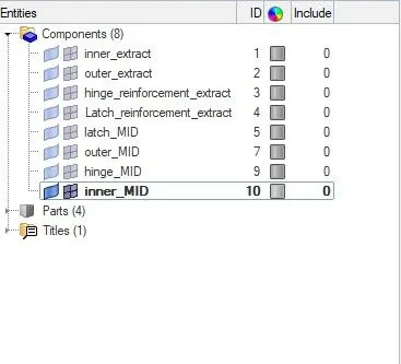
Fig 3: Organising mid surfaces with proper naming.
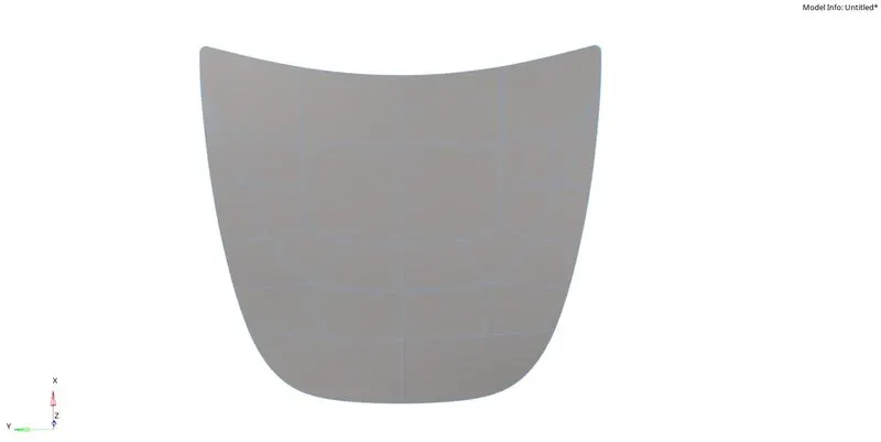
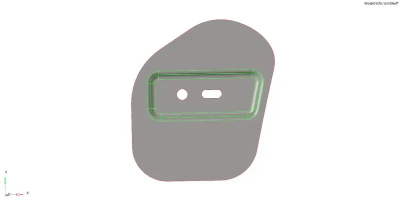
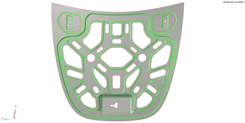
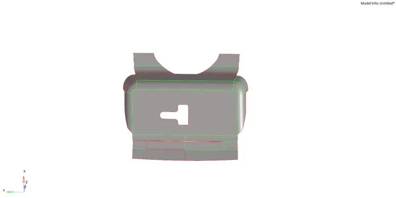
Fig 4: Extracted mid surfaces from the components.
4. After the extraction of mid surface, if there are any free edges within the surface, those are fixed by using surface and surface edit options.
5. Hiding all other components, we work on outer extract first. For achieving proper mesh flow, necessary splits are done on the mid surface in a rectangular manner. With the help of quick edit options, unwanted surface lines are toggled, and new ones are created with node to node or with node to line commands. Auto mesh is generated in each of the rectangular boxes, with five units as element size and mixed element type. Since the rectangular sections are made, all quad elements will be generated if any tria is formed in a particular area. They can be removed either by remeshing or with cleanup tools in the quality index. Other than these options dragging trias out of the mesh, combining two opposite trias, splitting, combining, and creating elements, generate maximum quads and least tria elements.
6. Smoothing and element optimization is done to ensure proper flow and orientation of the mesh. Finally, element check is done by assigning the criteria as:
Target Element Length = 5 Units
| S.N | Quality Criteria | Value |
| 1 | Aspect Ratio | 5 |
| 2 | Skewness | 45 |
| 3 | Warping | 15 |
| 4 | Taper | 0.5 |
| 5 | Min. Length | 2 Units |
| 6 | Max. Length | 8 Units |
| 7 | Min angle Quad | 45 |
| 8 | Max angle Quad | 135 |
| 9 | Min angle Tria | 20 |
| 10 | Max angle Tria | 120 |
| 10 | Tria % | 10 |
With these above criteria, the generated mesh is checked for each condition; if criteria fail to fall under the requirements, manual mesh methods can correct the mesh.
***Here, only half of the surface has meshed for the outer extract because it is perfectly symmetric along the longitudinal midplane. Upon successfully generating the mesh on either half, elements are duplicated and elected onto the other side to obtain a fully meshed surface.
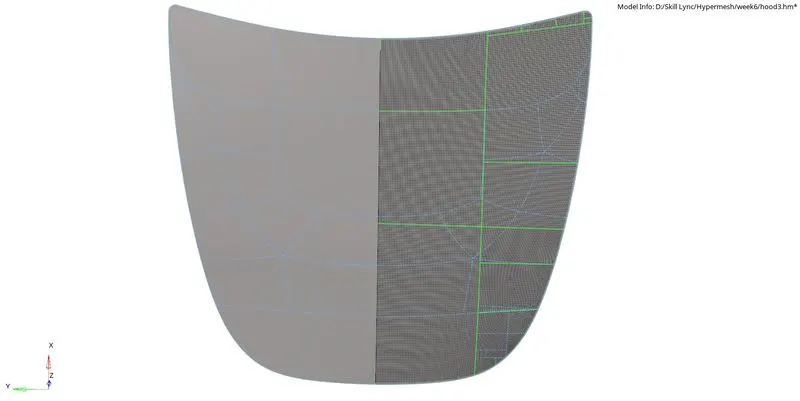
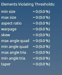
Fig 5: Meshed portion of the surface; quality index
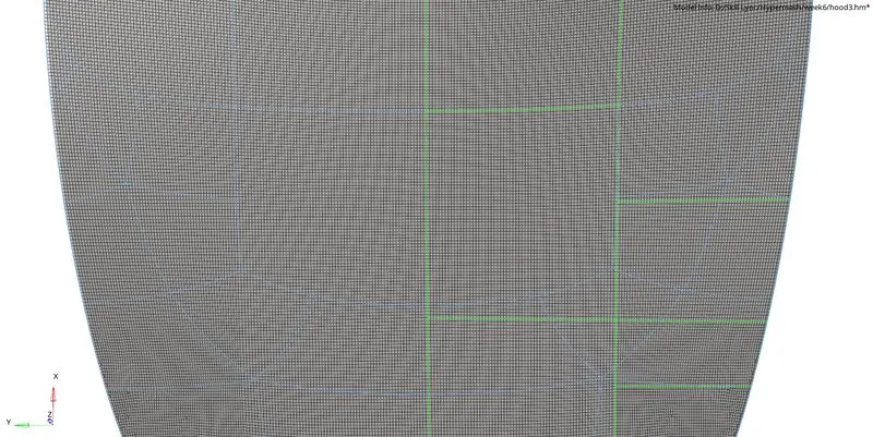
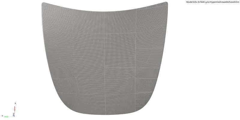
Fig 6: Zoomed in the mesh; Overall mesh of the surface after reflecting the elements to the symmetrical side.
7. Mesh and surface are hidden for the outer extract, and the inner extract surface is displayed. This surface also looks symmetrical except for the top latch portion, so only half of the surface is meshed, and then it can be reflected on the other side. Necessary surface splits are made to ensure proper mesh flow and maximum quad elements.
*** While doing splits in the surface, the features should not be altered drastically, and few feature edges cannot be suppressed because it disturbs the mesh, and element failure happens at those regions. Some of the feature edges should be preserved, and additional lines must be created accordingly.
When tria elements are formed, surrounding elements are selected along with the tia element and meshed again. It may be possible to remove the tria and create a quad element. Again this is a trial and error method to remove tria elements from the mesh. We aim to reduce trias as much as possible because tria elements are stiffer than quad elements; the presence of trias may result in inaccurate results.
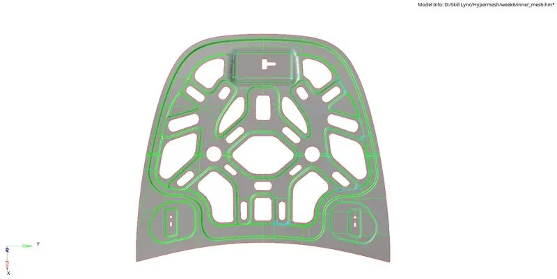
Fig 7: Necessary splits done on the right symmetrical surface.
Upon successfully meshing one side with resolving all the elemental issues, the elements are duplicated and reflected on the other side to get the complete meshing of the surface. After reflecting, check for the connectivity of nodes if any are disconnected; they can be connected with equivalence and replace options.
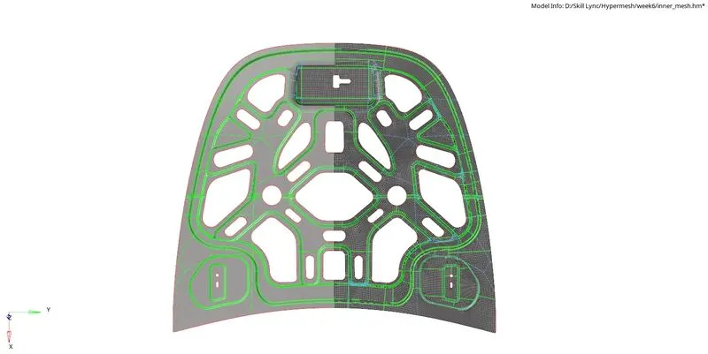
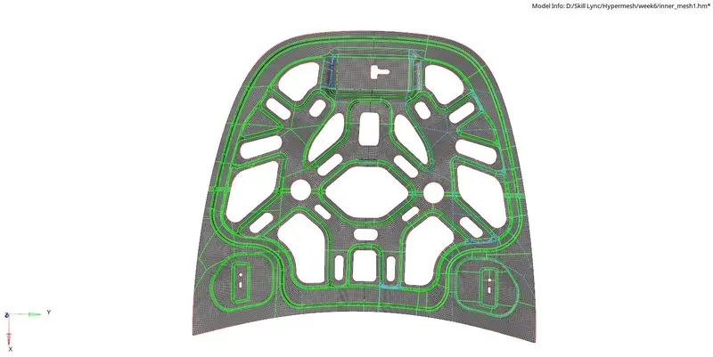
Fig 8: Mesh generated on one side of the surface; Reflected the elements onto the symmetrical side.
8. The same procedure is carried to mesh the other two surfaces (latch and hinge).
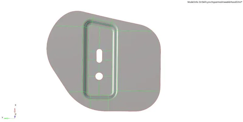
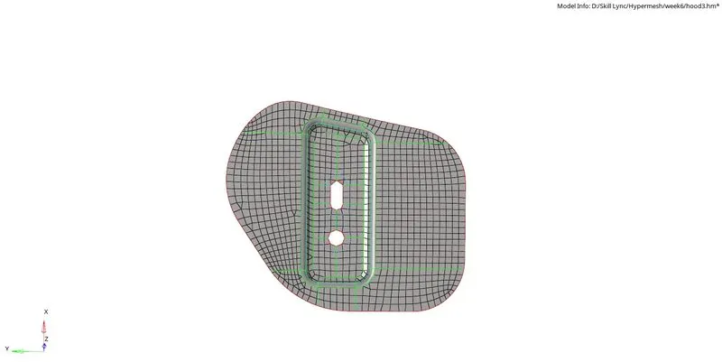
Fig 9: Splits on the surface of the hinge; Meshed hinge surface.
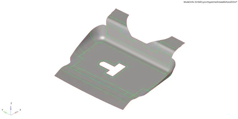
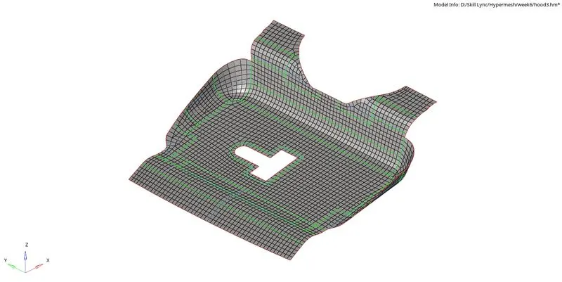
Fig 10: Splits on the surface of the latch; Meshed latch surface.
9. Create a new material named steel and assign the value of 'E', 'NU', and 'RHO". A new property is created to give thickness for the mid-surface with PSHELL as card image, and thickness of 1 unit is entered.
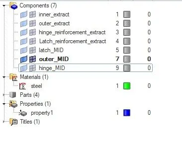
Fig 11: List of model items.
Conclusion: 2D mesh was generated on the hood component with an element length of 5 units, satisfying all the mentioned element criteria.
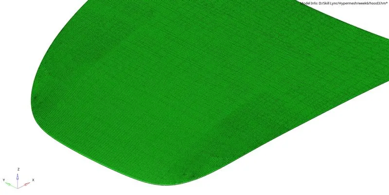
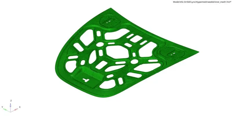
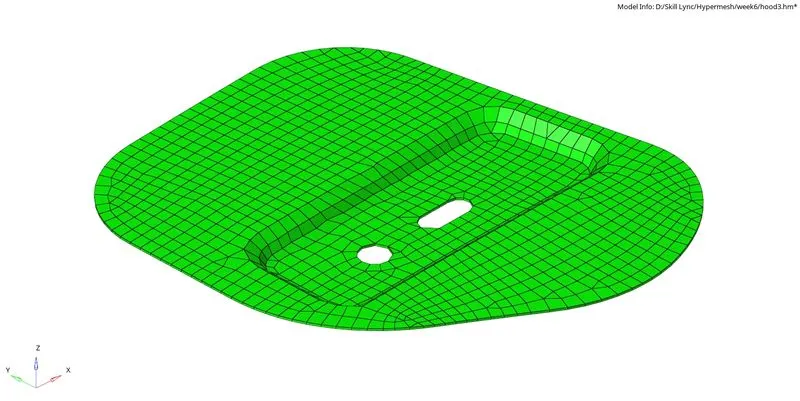
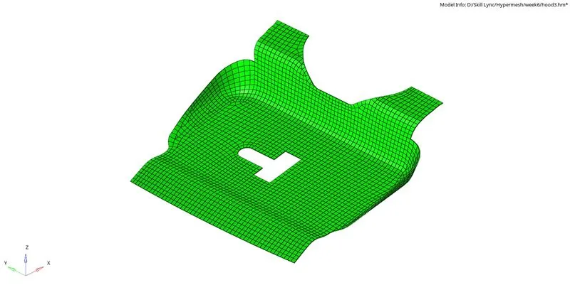
Fig 12: Detailed view of 2D mesh on every component of the hood.