1D Element Creation in Hypermesh
Objective: To Create 1D elements on a given component.
Procedure:
1. Import the given bracket component.
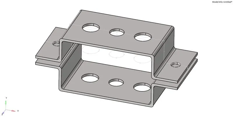
Fig 1: Imported geometry file.
2. Extract the mid surface from the solids using the skin offset method in the auto-extract option from the mid surfaces command.
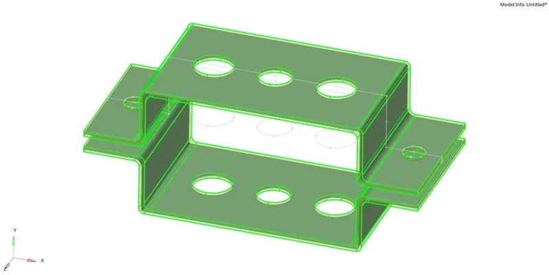
Fig 2: Extracted mid-surface from the solids.
3. Delete the solids so that only the surfaces are left.
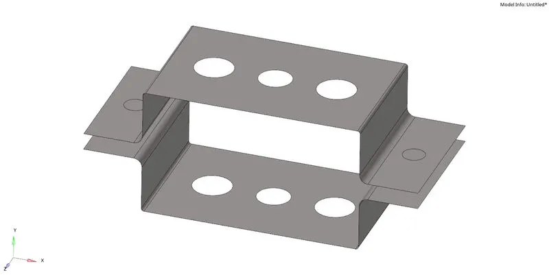
Fig 3: Deletion of solids.
4. Create a new component to assign the bottom surface of the bracket to the created component using the organise command in the tool options.
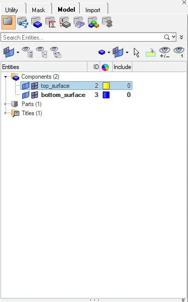
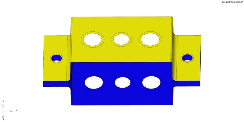
Fig 4: Created a new component named bottom_surface and assigned the bottom surface of the geometry to it.
5. Before moving on to meshing, washer splits are created with an offset of 5 units for the bigger circles and 2.5 units for the smaller circles. 2D meshing is done with five units element size with a mixed element type. The number of nodes on the circular edges and the offsets is made equal.
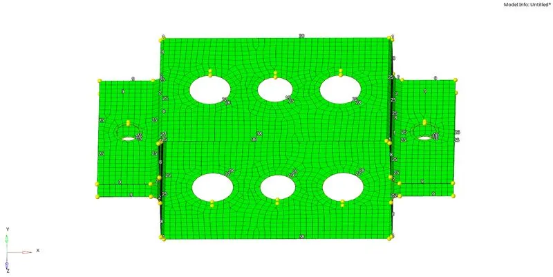
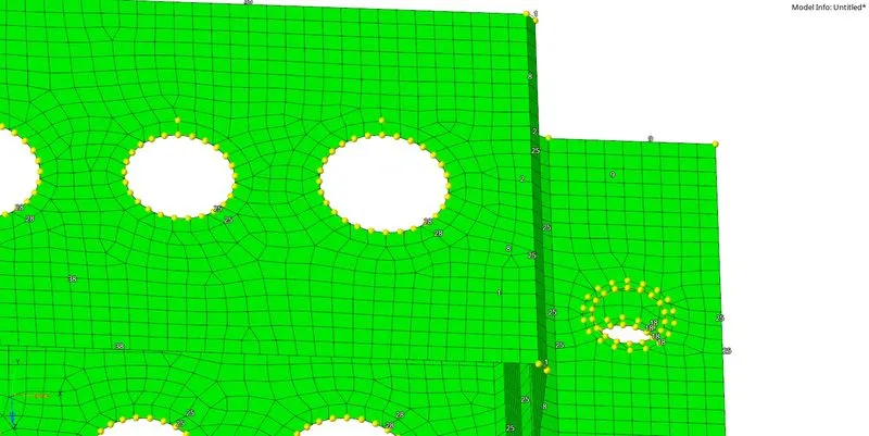
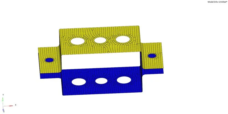
Fig 5: Meshed the extracted mid surfaces.
6. Create a material section in the tab area and name it steel. In the name-value area, select the card image as MAT1 and enter the G as 210000, Nu 0.3, and RHO as 7.85e-09.
7. Create a property for top and bottom surfaces in the tab area and assign the material as steel for both. In the card image, make it to PSHELL and give a thickness of 1 unit. In the components list, select the top_surface and bottom_surface to assign the created properties accordingly to set the components' thickness and material.
8. Navigate to the HyperBeam command in the 1D menu, check the standard selection option and click on create. A new window pops up in that different beam sections can be made, according to the given parameters :
- Cross-Section: BOX- Dimension a= 12 mm.
Dimension b=10 mm.
Thickness t= 0.75 mm.
- Cross-Section: I Section- Dimension a= 8 mm.
Dimension b= 10 mm.
Dimension c= 8.5 mm.
Thickness t1= 0.75 mm.
Thickness t2= .6 mm.
Thickness t3= .6 mm.
- Cross-section: X section- Dimension DIM1= 5 mm.
Thickness DIM2= 1.2 mm.
Dimension DIM3= 10 mm.
Thickness DIM4= 1.2mm.
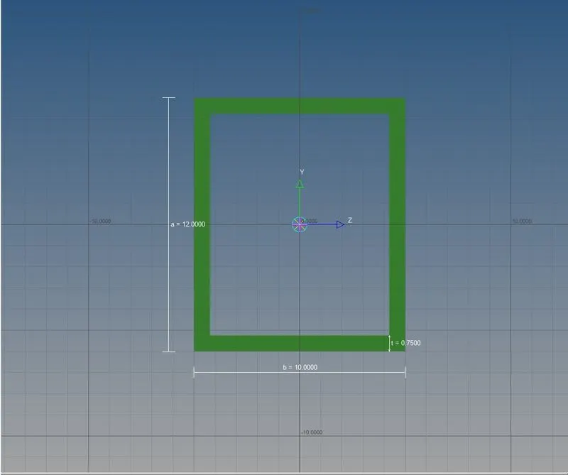
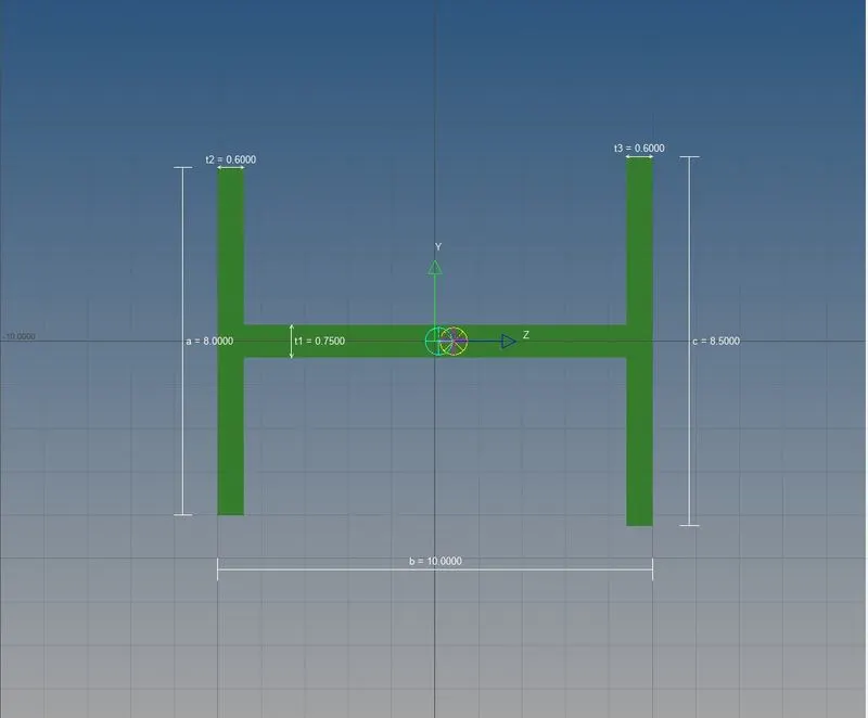
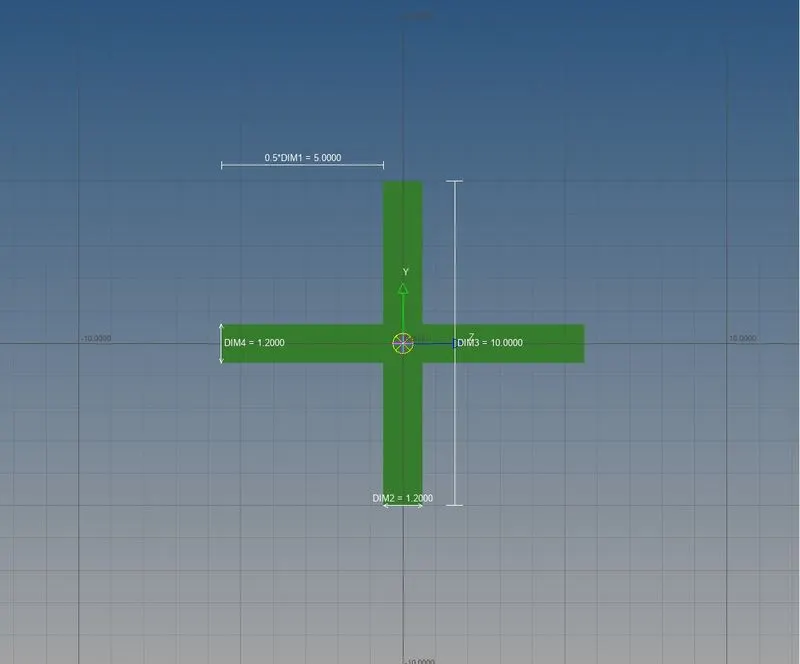
Fig 6: Created beam of a box, I, and X cross-sections with the mentioned parameters above.
9. Exit the window and create new properties for the rod, beam, and bar elements in the area. For the rod, select PROD as the card image, steel as material, and in the beamsec selection, pick the box section. For the beam, select PBEAM as the card image, steel as material, and in the beamsec selection, choose the I section. For the bar, select PBAR as the card image, steel as material, and in the beamsec selection, pick the X section. Create one more property for the spring element and choose the card image as PELAS.
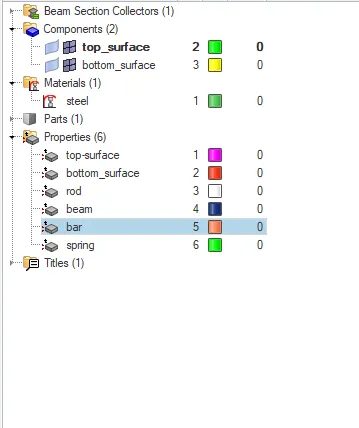
Fig 7: Showing different components, materials and properties created.
10. RBE2 rigid is created on the first circle of both the surfaces with translational DOF constrained. (1D, rigids).
11. RBE3 rigid is created on the middle circle of both the surfaces with all DOF constrained. (1D, rbe3).
12. RBE3 rigid is created on both surfaces' last circle, constraining only x and y DOFs. (1D, rbe3).
13. RBE2 rigid is created on the outer end circles of the bracket of both the surfaces with all DOF constrained. (1D, rigids).
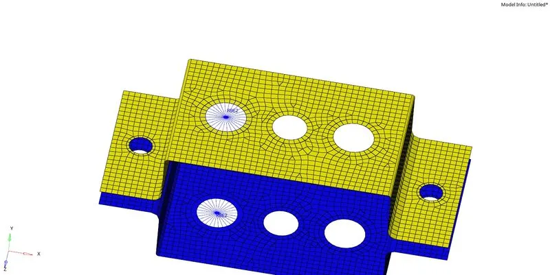
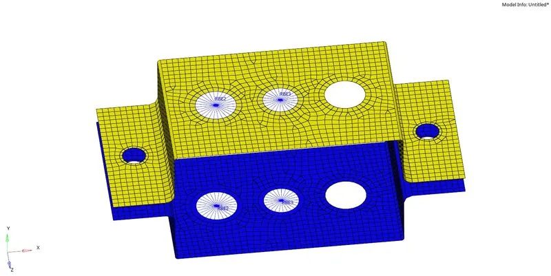
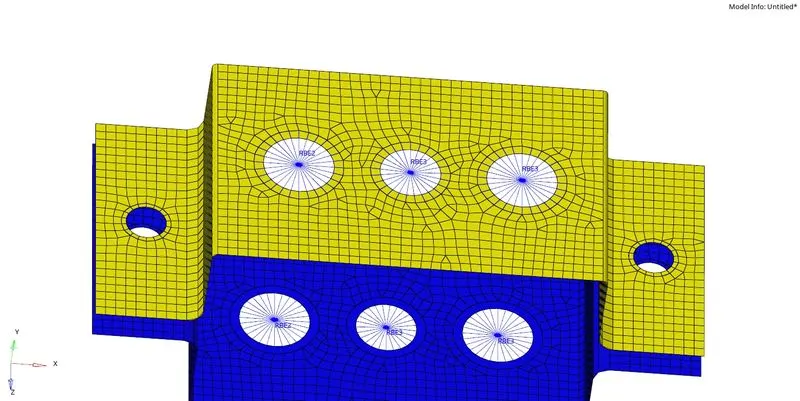
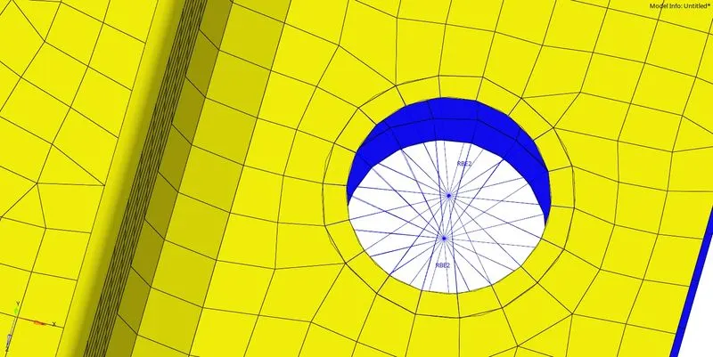
Fig 8: Different rigids are created on the circles.
14. A rod element is created connecting two central nodes of the RBE2 of the first circle with the property as rod and element type as CROD. (1D,rods).
15. A beam element is created connecting two central nodes of the RBE3 of the middle circle with the property as beam and element type as CBEAM. (1D,bars).
16. A bar element is created connecting two central nodes of the RBE3 of the last circle with the property as bar and element type as CBAR. (1D,bars).
17. The outer end circles of the bracket of both the surfaces, a mass is created with 10 magnitude on the central nodes of the RBE2 and choosing the element type as CMASS1. (1D,masses).
18. Central nodes of the extreme edges of the top and bottom surfaces in the longitudinal direction are selected to create a spring element with an element type CELAS1 and with a property of spring. (1D,springs).
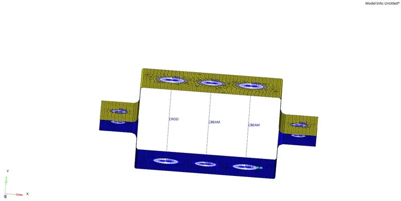
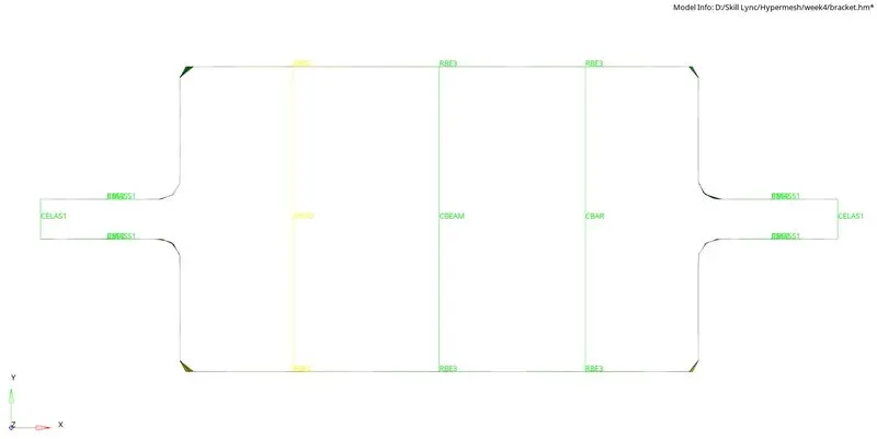
Fig 9: Different 1D elements are created.
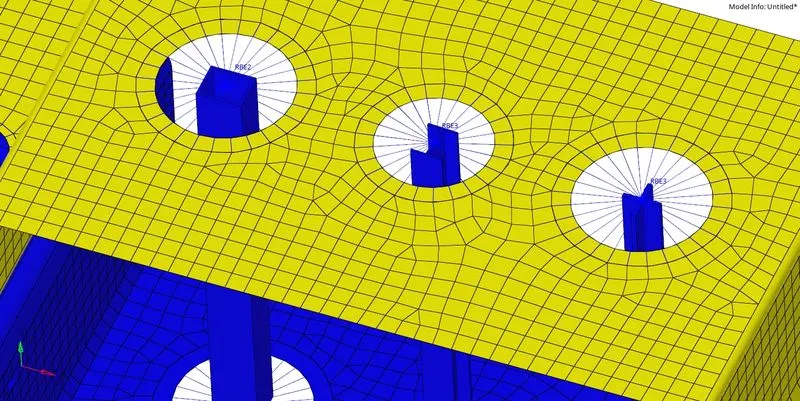
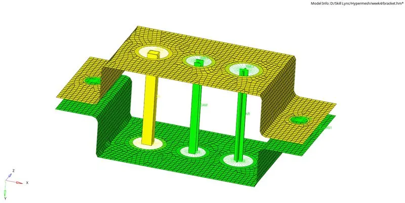
Fig 10: 1D detailed element representation.
Conclusion: 1D elements are created with the provided parameters for the given bracket component.
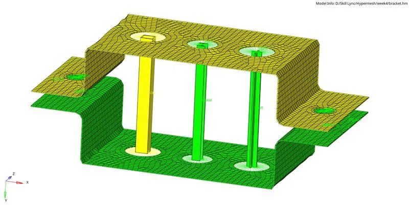
Fig 11: 1D and 2D detailed representation.