Meshing of Door Inner Panel in Hypermesh
Objective: To generate 2D mesh on the side door of a car.
Procedure:
1. Import the given geometry file into hypermesh.
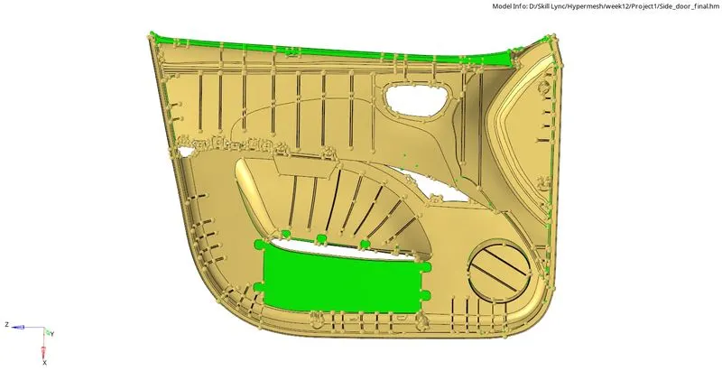
Fig 1: side door body geometry.
2. The geometry consists of so many ribs and supports with fillets less than our required element size, so defeaturing the fillets must be done to eliminate the element failure in these areas. To defeature them, head to the defeature option in the geometry tab and select the surfaces with fillets. Enter a search value of 0.1 and 5 as the minimum and maximum size. It automatically detects the fillet areas and tries to remove them.
3. The above step must be done for every rib.
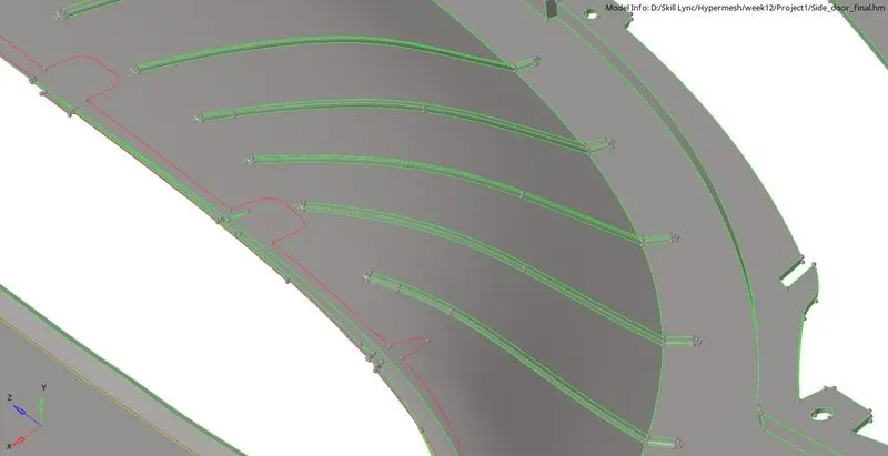
Fig 2: Different ribs in the geometry.

Fig 3: Option for defeaturing the fillet surfaces.
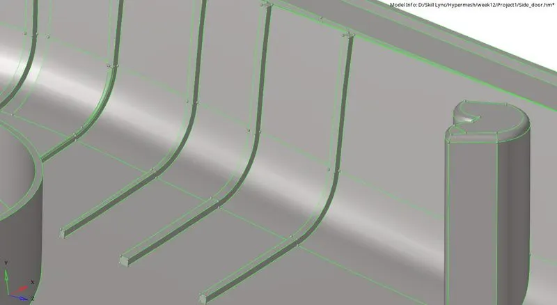
Fig 4: Ribs after removing the fillet surfaces.
4. Surface clean-up must be performed to eliminate any distorted surfaces and problematic areas before extracting mid-surface. Free edges must be removed inside the geometry.
5. The mid-surface for every feature in the geometry is extracted manually by calculating the thickness of the body and then offsetting it by the half distance. The ribs must also be offset by their thickness value, and finally, they are extended and attached to the main panel of the body. These are done using the surface edit options in the geometry tab. While doing the offset, make sure the normal of the surface is pointing out in the direction in which you require the surface; if not, reverse the normals.
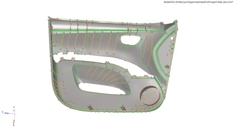
Fig 5: Generated mid-surface and attached the ribs to the panel.
6. The mid surface is cleared for any surface errors and is proceeded with meshing.
7. For achieving proper mesh flow, necessary splits are done on the mid surface in a rectangular manner. With the help of quick edit options, unwanted surface lines are toggled, and new ones are created with node to node or with node to line commands. Auto mesh is generated in each of the rectangular boxes, with five units as element size and mixed element type. Since the rectangular sections are made, all quad elements will be generated if any tria is formed in a particular area. They can be removed either by remeshing or with cleanup tools in the quality index. Other than these options dragging trias out of the mesh, combining two opposite trias, splitting, combining, and creating elements, generate maximum quads and least tria elements.
8. Smoothing and element optimization is done to ensure proper flow and orientation of the mesh. Finally, element check is done by assigning the criteria as:
Target Element Length = 4 Units
| S.N | Quality Criteria | Value |
| 1 | Aspect Ratio | 5 |
| 2 | Skewness | 45 |
| 3 | Warping | 15 |
| 4 | Taper | 0.5 |
| 5 | Min. Length | 2 Units |
| 6 | Max. Length | 6 Units |
| 7 | Min angle Quad | 45 |
| 8 | Max angle Quad | 135 |
| 9 | Min angle Tria | 20 |
| 10 | Max angle Tria | 120 |
| 10 | Tria % | 10 |
With these above criteria, the generated mesh is checked for each condition; if criteria fail to fall under the requirements, manual mesh methods can correct the mesh.
*** While doing splits in the surface, the features should not be altered drastically, and few feature edges cannot be suppressed because it disturbs the mesh, and element failure happens at those regions. Some of the feature edges should be preserved, and additional lines must be created accordingly.
When tria elements are formed, surrounding elements are selected along with the tia element and meshed again. It may be possible to remove the tria and create a quad element. Again this is a trial and error method to remove tria elements from the mesh. We aim to reduce trias as much as possible because tria elements are stiffer than quad elements; the presence of trias may result in inaccurate results.
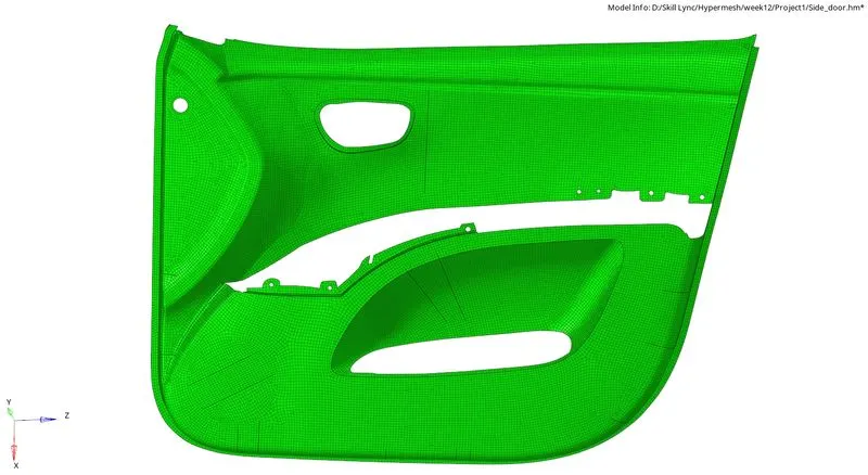
Fig 6: Generated mesh on the side door.
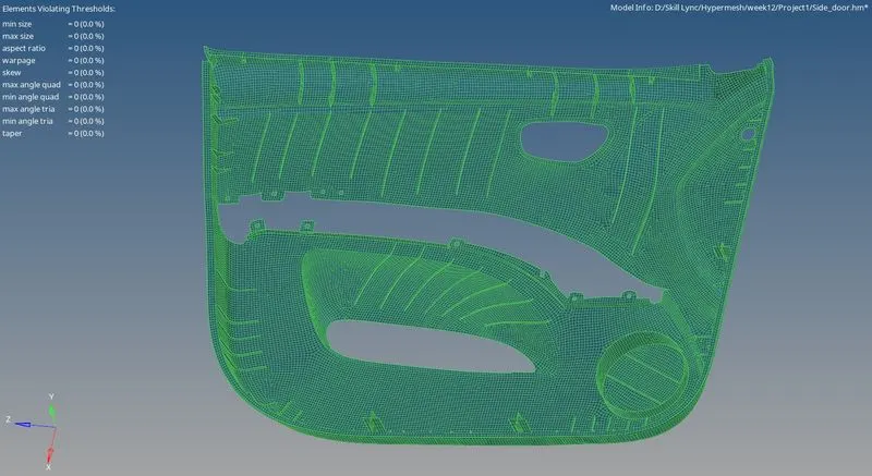
Fig 7: Elements satisfying all the given criteria.
9. The connectors are defined in the plus shape and are attached to the geometry.
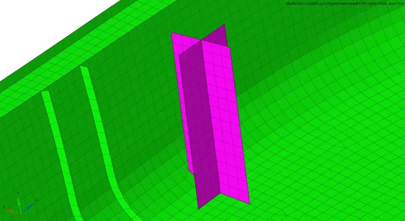
Fig 8: Connectors of the door.
10. Since the door has features with various thicknesses, the PSHELL property for every thickness is created separately, and the elements with these thicknesses are collected in separate components.
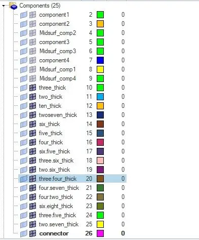
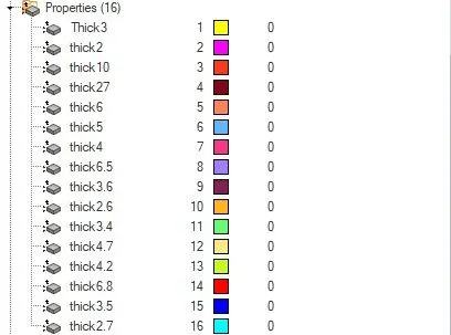
Fig 9: Components and properties for different thicknesses.
Conclusion: 2D mesh was generated on the side door component with an element length of four units, satisfying all the mentioned element criteria.
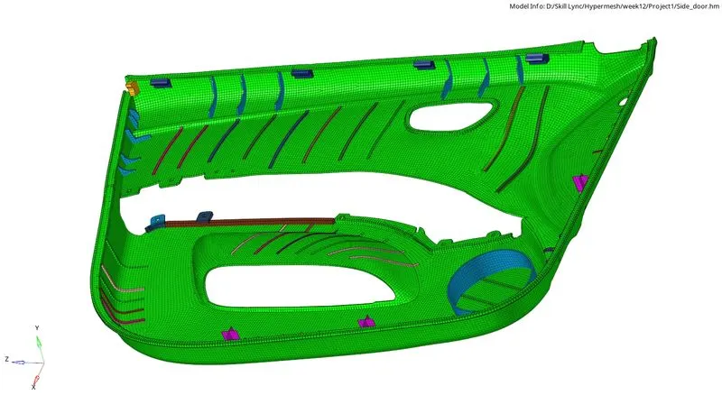
Fig 10: 2D detailed element representation of the side door mesh.