Week 9-Creation of 1D Connectors Challenge
Objective:-
For this model, I have to mesh the given geometry. Provided below are the quality parameters that you have to follow.
Target Element size - 5 Units
|
S.N |
Quality Criteria |
Value |
|
1 |
Aspect Ratio |
5 |
|
2 |
Skewness |
45 |
|
3 |
Warping |
15 |
|
4 |
Taper |
0.5 |
|
5 |
Min. Length |
2 Units |
|
6 |
Max. Length |
8 Units |
|
7 |
Min angle Quad |
45 |
|
8 |
Max angle Quad |
135 |
|
9 |
Min angle Tria |
30 |
|
10 |
Max angle Tria |
110 |
|
10 |
Tria % |
15 |
Create connector and Attach the various parts of the given model
1. Right_Rail_2 & Front_truss_1:- Seam-Quad(angled+capped+L)
2. Left_Rail_2 & Front_truss_1:- Quad elements
3. Front_truss_2, Front_truss_1 & Right_Rail_1:- Spot weld with 2 Layers and 5 mm Diameter
4. Front_truss_2, Front_truss_1 & Left_Rail_1:- Hexa (Adhesive)
5. Rear_truss_2 & Right_Rail_2:- Bolt Connector
6. Rear_truss_2 & Left_Rail_2:- Bolt Connector
7. Right_Rail_1 & Right_Rail_2:- Spot-weld with Rigid Elements
8. Left_Rail_1 & Left_Rail_2:- Spot-weld with Spring Elements
9. Rest all the component left Join them with suitable connectors.
Model (Before) :-
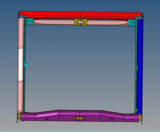
Procedure:-
1. Import the CAD model in the hypermesh.
2. Mesh the given components as per the given quality criteria.
Componet after meshing will look like.
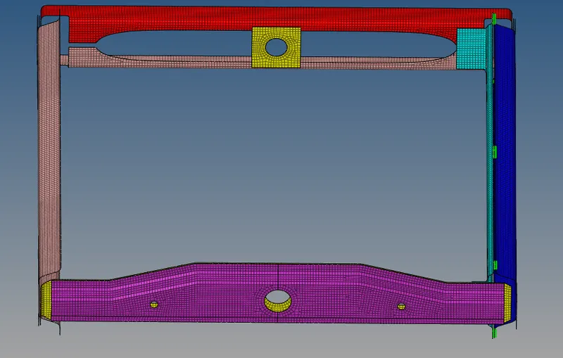
3. Check the quality of the mesh and improve it by fixing the failed elements.
4. Now start creating the Connections as given above.
For, Seam-Quad(angled+capped+L)
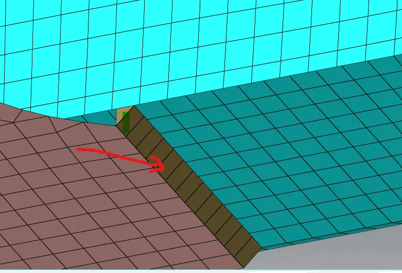
3. In 2D, Connectror browser select "Seam<type:Seam-Quad(angled+capped+L)" select the node list by path & give the spacing as per the element size i.e 5 and hit create. the connections will be created.
For, Spot weld with 2 Layers and 5 mm Diameter
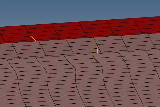
4. Select connector "Spot" and type as plot, select the nodes and components. Give the tolerance value of 10, 2 layer and dia. 5mm and hit create the spot connection will be created.
For, Hexa (Adhesive)
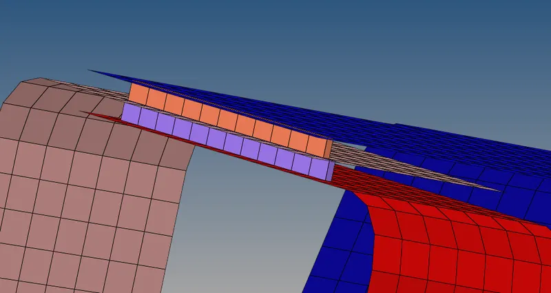
5. Select "Seam" and type as "hexa-adhesive", select the node path, keep one element behind from the edge while selecting the node. Keep the weld angle as desired (60 or 45). Hit create, the connection will get realised.
For, Bolt Connector
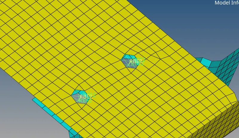
6. Select the connector as "Bolt" and type as "bolt (general)", select the node list and components, layers: as 2 and tolerance as 10 mm, hit create and the bolt connection will be realised.
7. Hence the final model is created.