Week 9-Creation of 1D Connectors Challenge
AIM:
For this challenge, you will have to mesh the given geometry. Provided below are the quality parameters that you have to follow.
Target Element size - 5 Units
|
S.N |
Quality Criteria |
Value |
|
1 |
Aspect Ratio |
5 |
|
2 |
Skewness |
45 |
|
3 |
Warping |
15 |
|
4 |
Taper |
0.5 |
|
5 |
Min. Length |
2 Units |
|
6 |
Max. Length |
8 Units |
|
7 |
Min angle Quad |
45 |
|
8 |
Max angle Quad |
135 |
|
9 |
Min angle Tria |
30 |
|
10 |
Max angle Tria |
110 |
|
10 |
Tria % |
15 |
Create connector and Attach the various parts of the given model
1. Right_Rail_2 & Front_truss_1:- Seam-Quad(angled+capped+L)
2. Left_Rail_2 & Front_truss_1:- Quad elements
3. Front_truss_2, Front_truss_1 & Right_Rail_1:- Spot weld with 2 Layers and 5 mm Diameter
4. Front_truss_2, Front_truss_1 & Left_Rail_1:- Hexa (Adhesive)
5. Rear_truss_2 & Right_Rail_2:- Bolt Connector
6. Rear_truss_2 & Left_Rail_2:- Bolt Connector
7. Right_Rail_1 & Right_Rail_2:- Spot-weld with Rigid Elements
8. Left_Rail_1 & Left_Rail_2:- Spot-weld with Spring Elements
9. Rest all the component left Join them with suitable connectors.
PROCEDURE:
- Download the model from the assessment.
- Import that file in the hyper mesh.
- The given file is mid surface so, we directly go for the meshing for the all components.
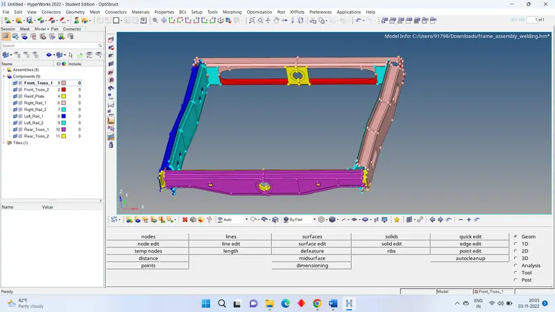
- Go to 2D > AUTO MESH > SELECT THE SURFACE > GIVEN ELEMENT SIZE AS = 5 > MESH.
- Press f10 and check any element is failing with quality parameter. If failing correct the element quality.
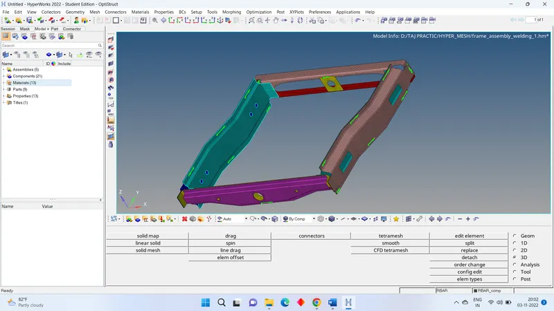
- It is time for connection. As mentioned in the question give the proper connection for particular parts.
CONECTIONS:
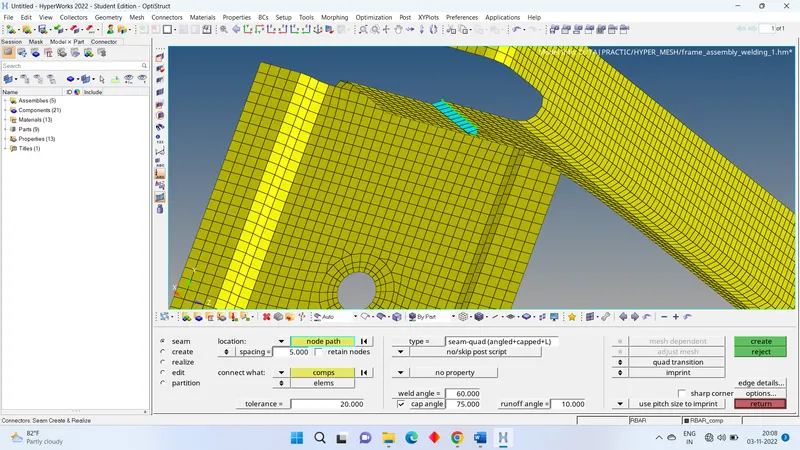
SEAM- QUAD (angled+capped+L)
- We have view on mesh part the RIGHT_RAIL_2 & FRONT_TRUSS_1
- Now go to the 2d > connector > seam > location= node path > type = angled+capped+L > SPACING= 5 > SELECT THE COMPONENTS > TOLERANCE= 20 > CREATE.
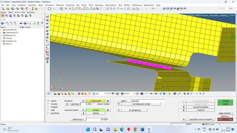
QUAD ELEMENTS
- We have view on mesh part the RIGHT_RAIL_2 & FRONT_TRUSS_1
- Now go to the 2d > connector > seam > location= node path > type = quads > SPACING= 5 > SELECT THE COMPONENTS > TOLERANCE= 20 > CREATE.
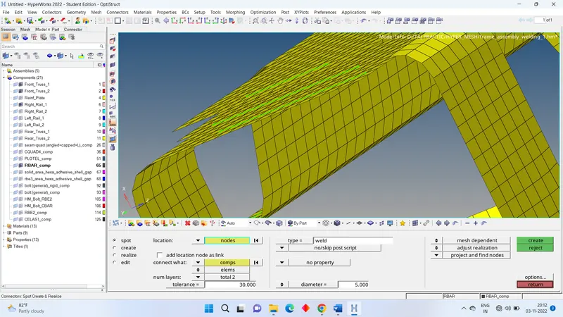
SPOT WELD with 2 LAYER and 5 mm diameter.
- We have view on mesh part the RIGHT_RAIL_1 & FRONT_TRUSS_2 & FRONT_TRUSS_1
- Now go to the 2d > connector > SPOT > location= node path > type = WELD > DIAMETER = 5 > SELECT THE COMPONENTS > TOLERANCE= 30 > CREATE.
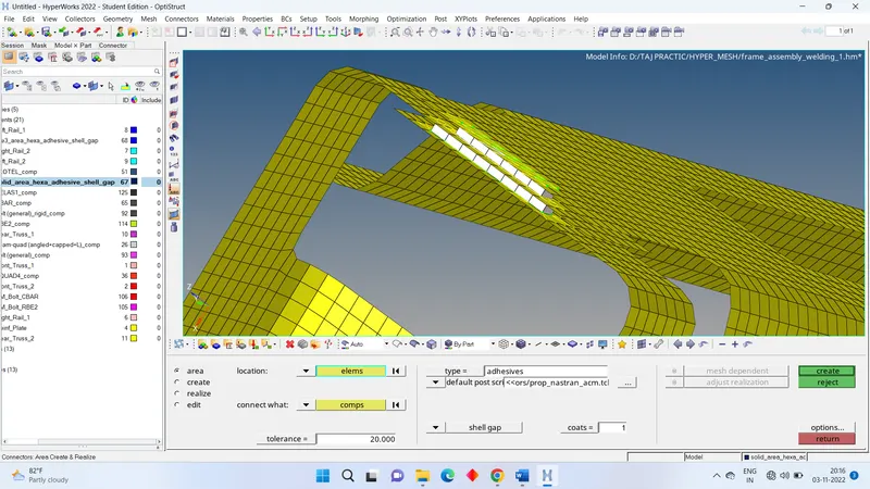
HEXA ADHESIVE
- We have view on mesh part the LEFT_RAIL_1 & FRONT_TRUSS_2 & FRONT_TRUSS_1
- Now go to the 3d > connector > AREA > location= node path > type = adhesive > SELECT THE COMPONENTS > TOLERANCE= 30 > CREATE.
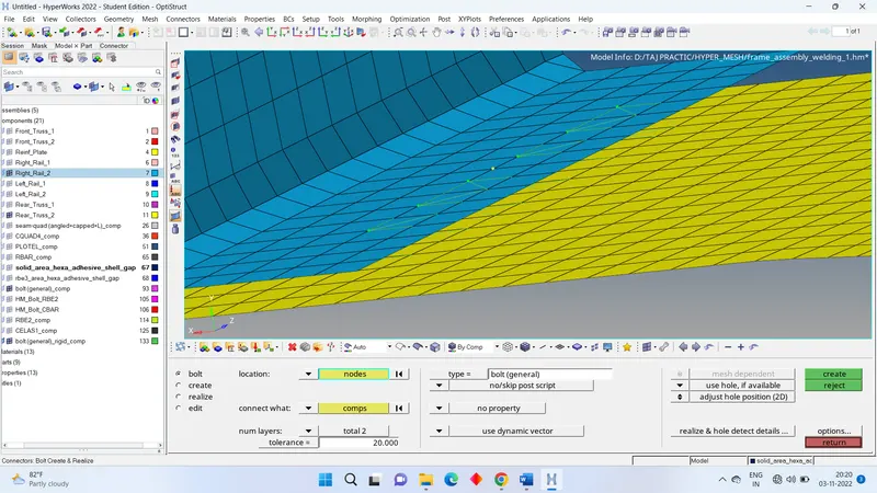
5 & 6. BOLT CONNECTOR
- We have view on mesh part the RIGHT_RAIL_1 & REAR_TRUSS_2.
- Now go to the 2d > connector > BOLT > location= node path > SELECT THE COMPONENTS > TYPE=BOLT(GENERAL) > TOLERANCE= 30 > consider existing holes only= use hole of available > CREATE.
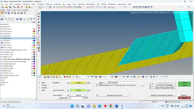
- now we have other part to repeat the bolt connection for that. Go to components and on mesh of REAR_TRUSS_2 & LEFT_RAIL_2.
- Now go to the 2d > connector > BOLT > location= node path > SELECT THE COMPONENTS > TYPE=BOLT(CBAR) > TOLERANCE= 30 > consider existing holes only= use hole of available > CREATE.
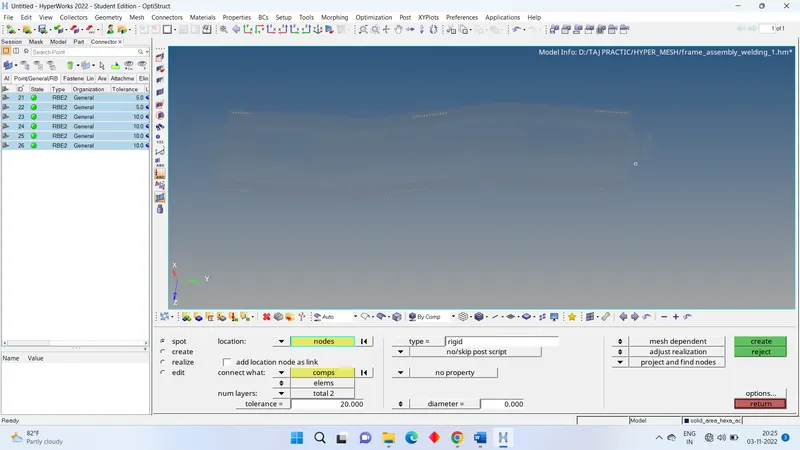
SPOT WELD with RIGID ELEMENTS
- We have view on mesh part the RIGHT_RAIL_1 & REAR_RAIL_2.
- Now go to the 2d > connector > SPOT > location= node path > type = RIGID > SELECT THE COMPONENTS > TOLERANCE= 30 > CREATE.
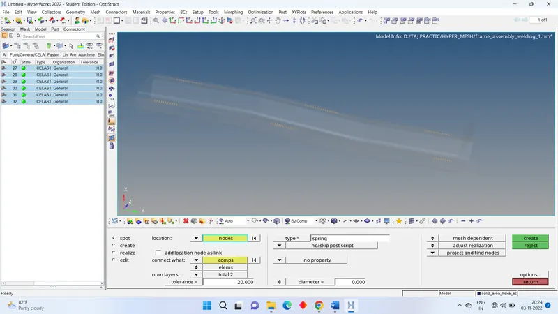
SPOT WELD with SPRING ELEMENTS
- We have view on mesh part the RIGHT_RAIL_1 & REAR_RAIL_2.
- Now go to the 2d > connector > SPOT > location= node path > type = SPRING > SELECT THE COMPONENTS > TOLERANCE= 30 > CREATE.
Learning outcomes:
- how to make different types of connections.
- how to identify the different types of connections.