Week 9-Creation of 1D Connectors Challenge
Objective-
For this challenge, you will have to mesh the given geometry. Provided below are the quality parameters that you have to follow.
Target Element size - 5 Units
|
S.N |
Quality Criteria |
Value |
|
1 |
Aspect Ratio |
5 |
|
2 |
Skewness |
45 |
|
3 |
Warping |
15 |
|
4 |
Taper |
0.5 |
|
5 |
Min. Length |
2 Units |
|
6 |
Max. Length |
8 Units |
|
7 |
Min angle Quad |
45 |
|
8 |
Max angle Quad |
135 |
|
9 |
Min angle Tria |
30 |
|
10 |
Max angle Tria |
110 |
|
10 |
Tria % |
15 |
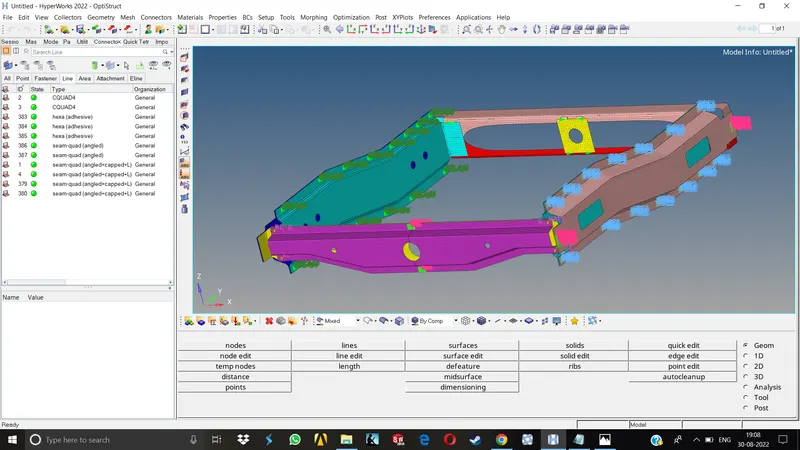
Create connector and Attach the various parts of the given model
1. Right_Rail_2 & Front_truss_1:- Seam-Quad(angled+capped+L)
2. Left_Rail_2 & Front_truss_1:- Quad elements
3. Front_truss_2, Front_truss_1 & Right_Rail_1:- Spot weld with 2 Layers and 5 mm Diameter
4. Front_truss_2, Front_truss_1 & Left_Rail_1:- Hexa (Adhesive)
5. Rear_truss_2 & Right_Rail_2:- Bolt Connector
6. Rear_truss_2 & Left_Rail_2:- Bolt Connector
7. Right_Rail_1 & Right_Rail_2:- Spot-weld with Rigid Elements
8. Left_Rail_1 & Left_Rail_2:- Spot-weld with Spring Elements
9. Rest all the component left Join them with suitable connectors
Procedure-
1.Import the given geometry in Hypermesh.
2.Set the proper quality criteria for meshing.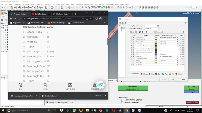
3.Proceed with meshing the components one by one.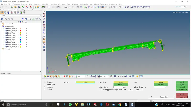
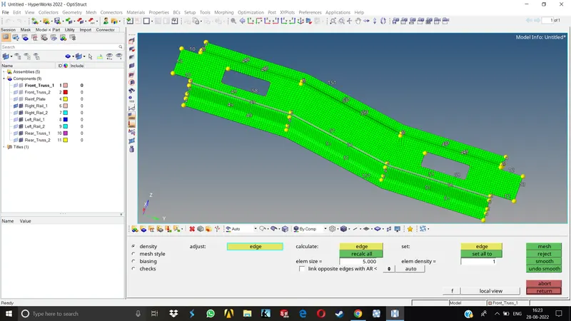
4.Look for failing elements, improper mesh flow and resolve those errors accordingly.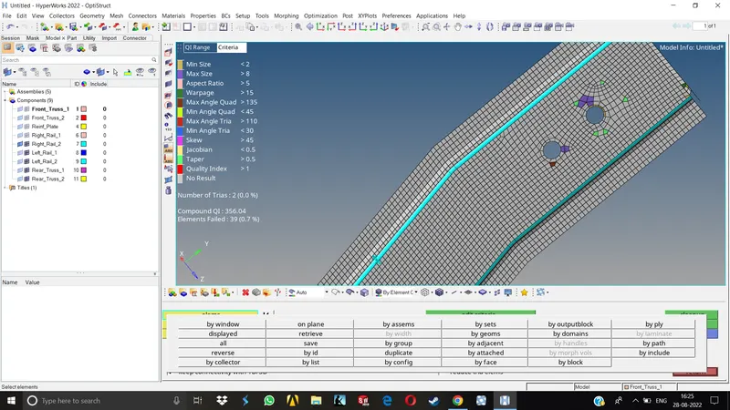
5.After all the components pass the quality check we can proceed with the connections.
Creating connections-
1. Right_Rail_2 & Front_truss_1:
Hide all the other components through the tree and keep visible only these two as this will be much easier to work on.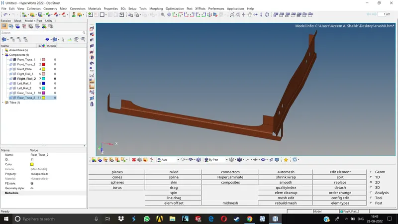
The connection we need to create here is Seam-Quad(angled+capped+L)
Go to 1D>Connectors>Seam now select Seam-Quad(angled+capped+L) in type menu.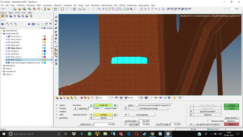
Now select the nodes by path on which you want to establish the connection and select the components. We can also change the weld,cap & runoff angle as desired.Hit create to proceed. the connection formed can be seen visually.
If we want to change some configurations of the connection we can go to the View >Browsers>Hypermesh>Connectors to open the connections tab.
2.Left_Rail_2 & Front_truss_1:
Keep above mentioned components visible only.
The connection we need to create here is Quad elements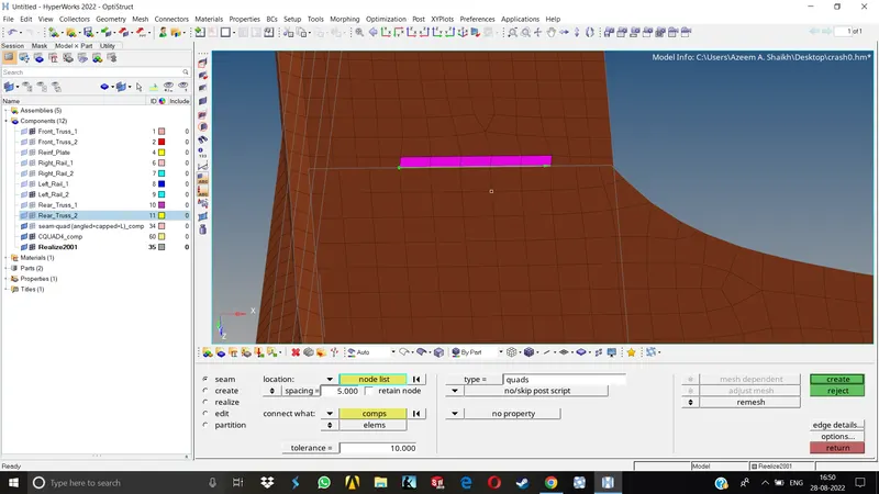
The procedure till selecting the type is same. Just select Quad elements by going into the type menu in seam connector. Select the nodes and components. The weld,cap&Runoff angle cannot be chamged in this type of connection.
3.Front_truss_2, Front_truss_1 & Right_Rail_1 :
The connection we need to establish here is Spot weld with 2 Layers and 5 mm Diameter.
Go to 1D>Connectors>Spot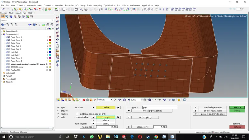
Set the no of layers as 2, dia as 5mm and type as Weld. Give proper search distance for the components (Tolerance). Select the nodes and components and click create. The connection will be done automatically.
4.Front_truss_2, Front_truss_1 & Left_Rail_1:
The connection type is Hexa (Adhesive)
Go to 1D>Connectors>Seam>Type>Hexa(adhesive)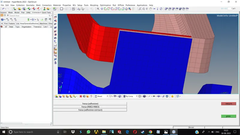
Choose the nodes on which you want to establish the connection. We'll keep the strips and coast as it is but we need to provide the proper width, selection of improper width will result in failure of realization for the elements.
Now choose the components and hit create.
5.Rear_truss_2 & Right_Rail_2 same for Rear_truss_2 & Left_Rail_2:
The type of connection need to established here is Bolt Connector.
Go to 1D>Connectors>Bolts
Here, as the given geometry has no holes for bolt connections, we need to change the setting here to, Create a hole if none. 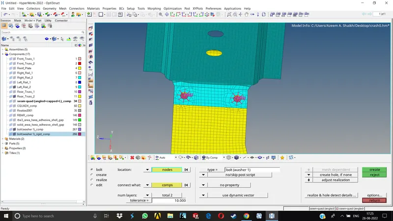
As there are lot of types of bolt connectors like with washers, without washers etc, it is always a good practice to capture the bolt connection with washer elements. If there is enough space available on the component for capturing the waher and the meshflow after capturing is remaining good, we should always go for bolt with washers.
Here, we just need to select a single node as the hole will automatically created around this node.
Select the components and hit create. The bolt connection will be established.
6.Right_Rail_1 & Right_Rail_2
Type of connection needed is Spot-weld with Rigid Elements
Go to 1D>Connectors>Spot>Type>Rigid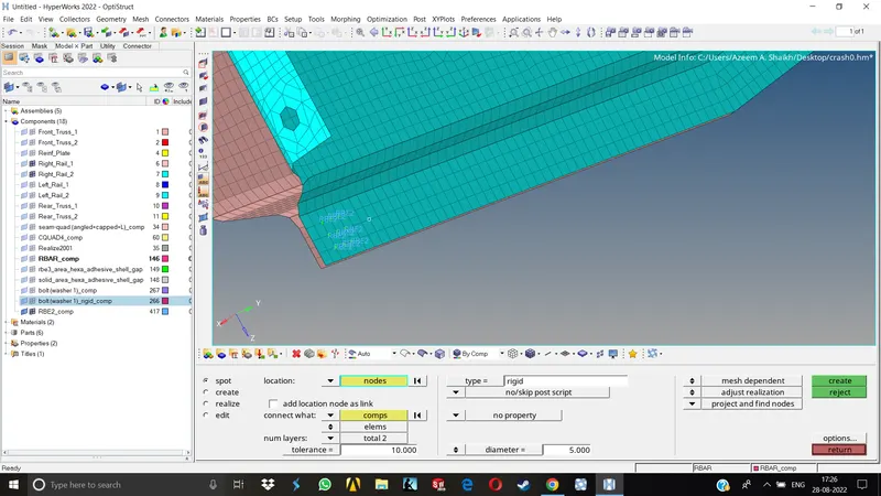
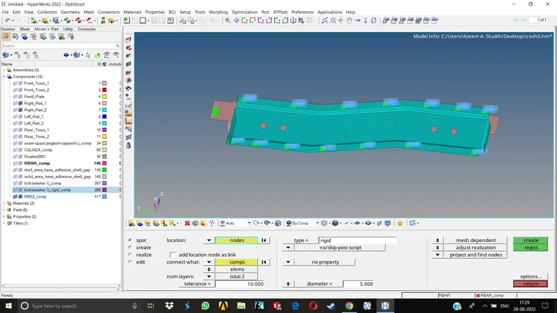
Select the nodes of the proper component, select the two components needed to be attached and hit create.
For creating the spring elements, just change the type from rigid to spring, all other things remains the same.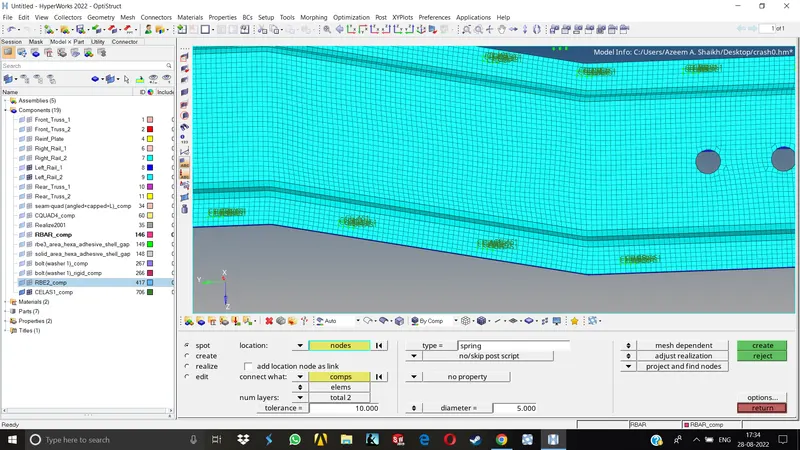
For remaining connections, we need to observe the entire model for any left over connections and establish the remaining ones.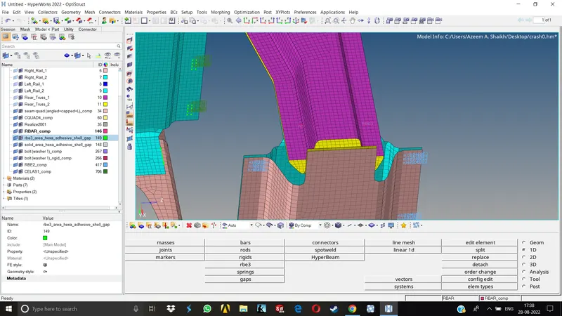
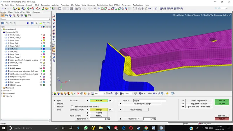
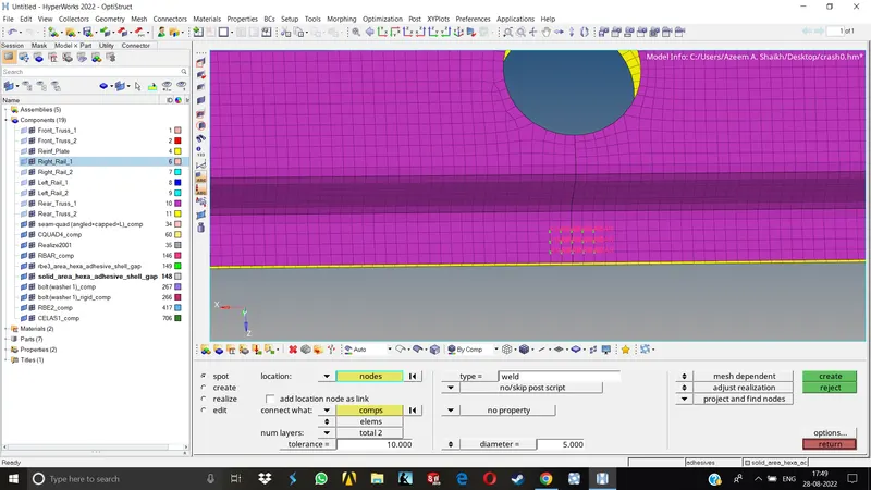
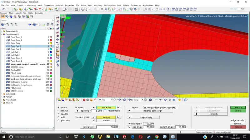
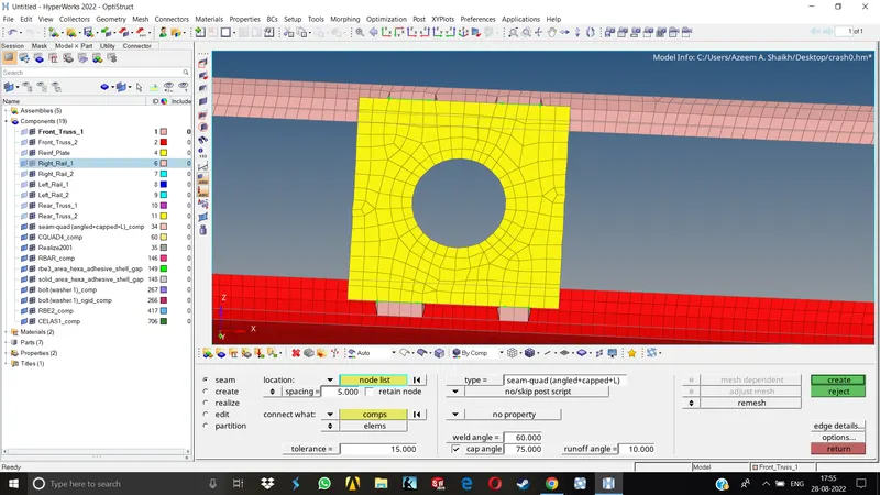
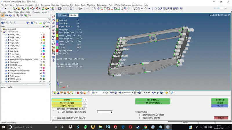
After all the connections are done, once again we need to check for quality failures if any and take care of them accordingly. Once we done with element cleanup, our model is ready.
Results:-
In this particular exersice, we learnt how to give proper connections to the FE model, dealing with the connections that are failing to realize, finding out the reason why the connections are failing (troubleshooting) and deal with them accordingly.
Final Model-