Week - 4 - 2D meshing for Plastic components
Aim-For the given Plastic Bottle Cap model, check for the geometrical errors and take the mid surface by suitable mid surfacing techniques. PID and Thickness assignment has to be done for all the mid surfaces. Mesh the same with given element Quality criteria.
Procedure-
- Download the given model and open the same in ANSA.
- Go to Mesh module>Perimeters>Length and set 1mm length for both Perimeter & Macros to eliminate visual distortions.
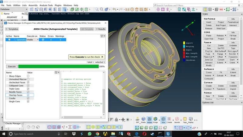
- Now go to Tools>Checks > Geometry for resolving the Geometrical errors.
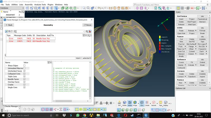
- Fix the geometrical errors and run the Geometry check once again for confirmation.
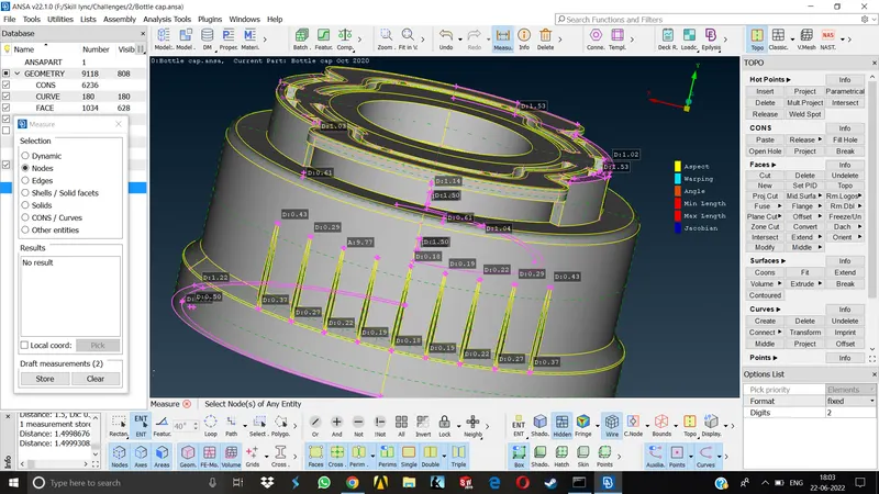
- As this component is a plastic component, some of the areas will have varying thickness. For taking proper midplane of such components it is always better to measure all the important areas and store thier values.
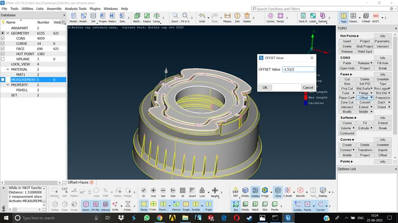
- Now we can start taking Midsurface for simpler areas by using Faces> Offset command. Select the face , enter the offset value and middle click.
- Complex areas will require more advanced commands like Curves>Middle, Cons>Project, Faces>Middle. It is a good practice to store the midsurface in a different lock view or assign a property.
- As this component has many complicating regions, it is not very straightforward to measure the thickness between two regions to give the offset. In order to measure the thickness correctly we have to take a sectional view of the model by using NOT command and selecting only half the body in order to measure the thickness properly.
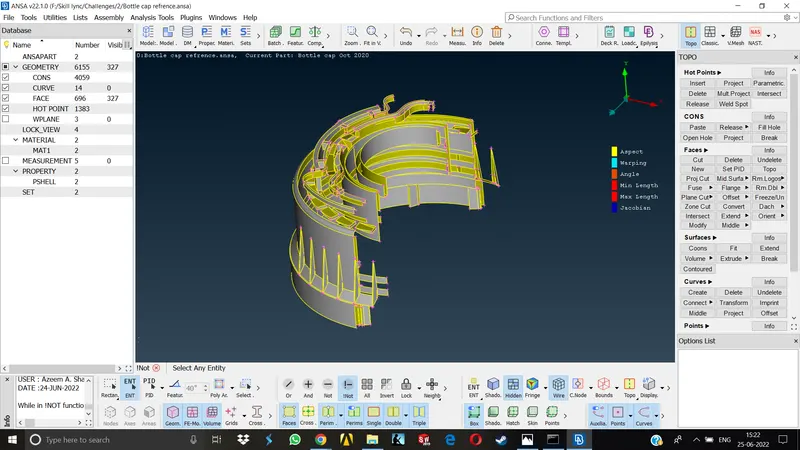
- Taking MId of some complicated areas require us to first capture the area between two cons by using Curves>Middle Then project this line on the midplane area and then create a new face for capturing the midplane.
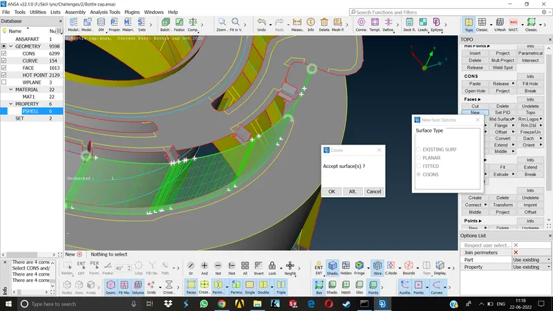
- There were many areas where we had to project the curves and create new faces for taking the mid surface.Taking MIdplane of this bottle cap was a little complicated than the previous hood model.
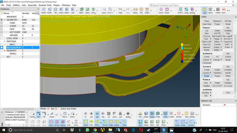
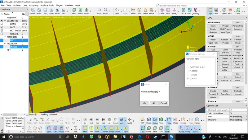
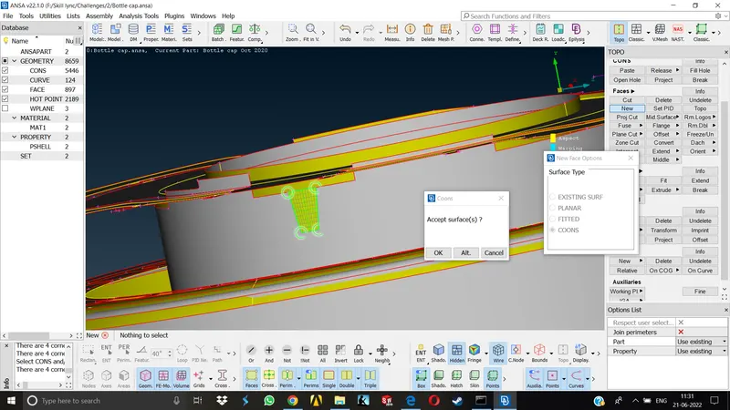
11. Taking Mid of the threads was quite easy as it was already explained in the FAQ section.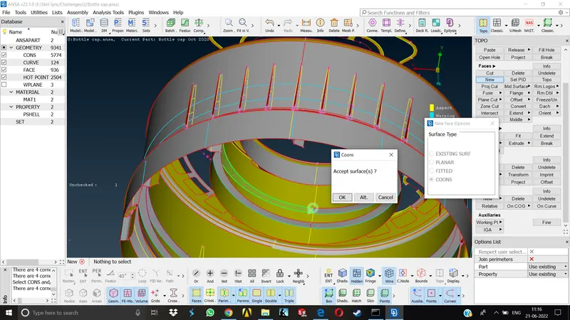
12.Once the midsurface was taken sucessfully by using above methods, It was time for assigning separate property and thickness to all the areas. As discussed earlier, all the necessary measurements were already stored.we only had to confirm those measurements for the respective areas and assign thickness to them.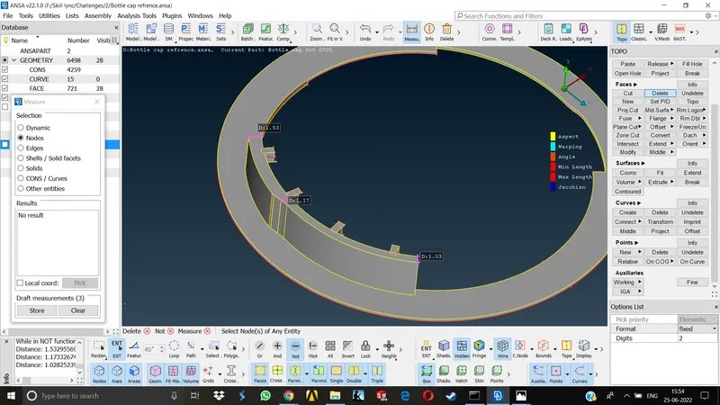
13.There were parts having varying thickness, As I was told by a support engineer , I calculated the average thickness for all the parts having varying thickness and applied them in the property card.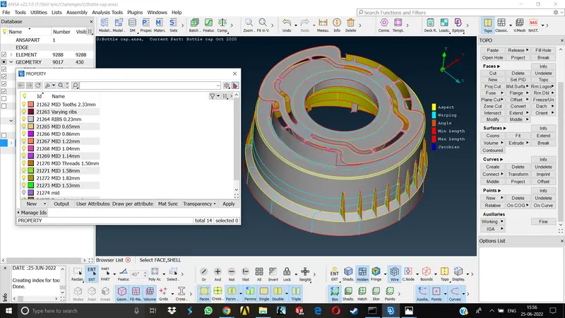
MESHING-
As the Midsurface is taken successfully we can proceed to meshing.
14. Prepare the surface for meshing by removing all the construction lines from the geometry. These lines will be complicating the meshflow and are responsible for failure of elements.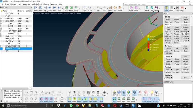
15. Wherever there was conjestion of these construction lines, we have to delete them by using Faces>Cut and selecting the line.We should keep all the feature lines as it is as long as its not causing the element failure, otherwise we have to defeature.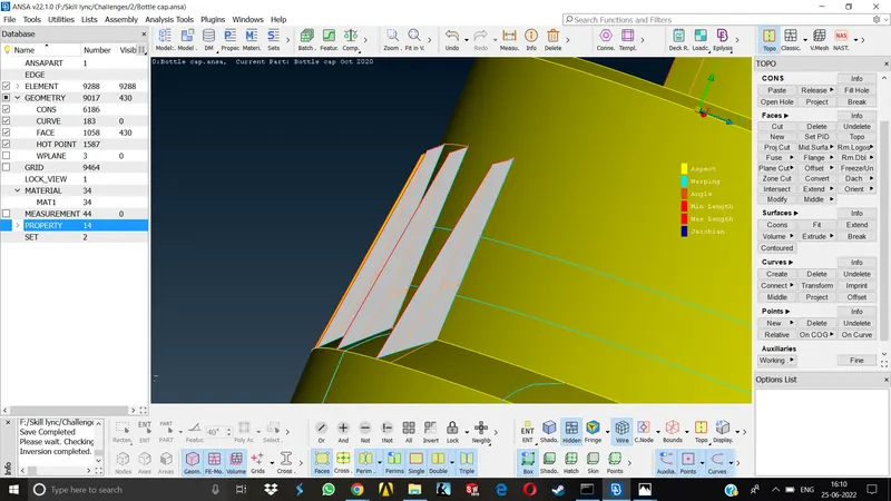
16.Once all the construction lines are taken care of, we can set the element length as required by going to Mesh module>Perimeters>Length also set the length for the Macros the same way.
17.Now we can set the Quality criteria by pressing the shortcut key F11.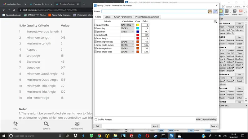
18.Similarly we can set the Mesh parameters by going to shortcut button for the same at the top middle menubar or going to Utilities>Mesh Parameters and set the target length, min. length and all other properties regarding the same.
19. Once above settings are done, we can now start meshing. Start at the complicated areas. Turn on the Hidden Mode to see the Quality errors and Meshing Statistics.
20. Go to Mesh module>Mesh Generation>Best and select the area on which meshing has to be done.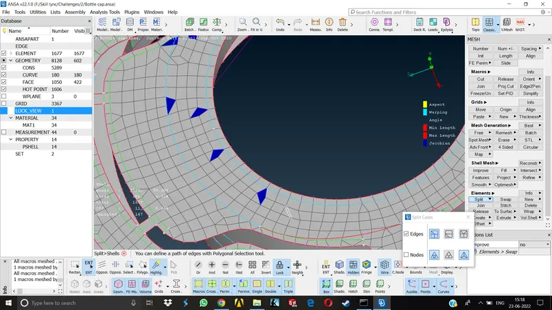
21.Use Reconstruct, Improve,Smooth,Split etc commands for dealing with the off elements, We can also use the Perimeters> Num+- command to vary the no of nodes & perform some trial and error and see the off elements are improving or not.
22.Similarly mesh all the areas and deal with the trias and off elements properly and complete the meshing.
23.After meshing is done we can again go to Quality criteria >Presentation parameters> Draw shell as solid and turn it on.
Learning Outcomes
1. Taking Midplane in complicated areas -
Using various commands like Curves>Middle, Curves > Project, Cons> Project and finally creating a new surface using Faces>New if the surface is regular or using Surfaces> Extrude if surface is irregular.
2.After performing above operations, in some of the cases extra faces would be produced.To deal with this,one can use Faces>Intersect command and select the first and second surfaces then the window will pop up asking to keep or delete all the attached surfaces.
3.Gained some speed in performing basic operations.
4.Gained the basic approach to deal with the plastic components.
Conclusion-
1.As this was my first time dealing with plastic component, taking the midplane for complicated areas was bit of a challenge.AT first it seemed difficult to take midplane but after some guidance of support engineers & some practice it was all good.
2.I learnt a lot of new commands while dealing with this particular components Mid.
3.Besides the Midsurface, everything else was pretty similar to the previous component.Basically once the midsurface is acquired correctly, meshing is not that difficult as we repeat the same commands while performing Mesh.
NOTE- Midsurface is in the Lockview.