Week 3 - 2D meshing for sheet metal
Aim-For the given Hood model, Take the mid surface for all the components after checking the geometrical errors and mesh the mid surface with the given element Quality criteria.
Procedure-
- Download the model given for the challenge by entering into the challenge.
- The file is in .stp format. Open the same file in the ANSA.
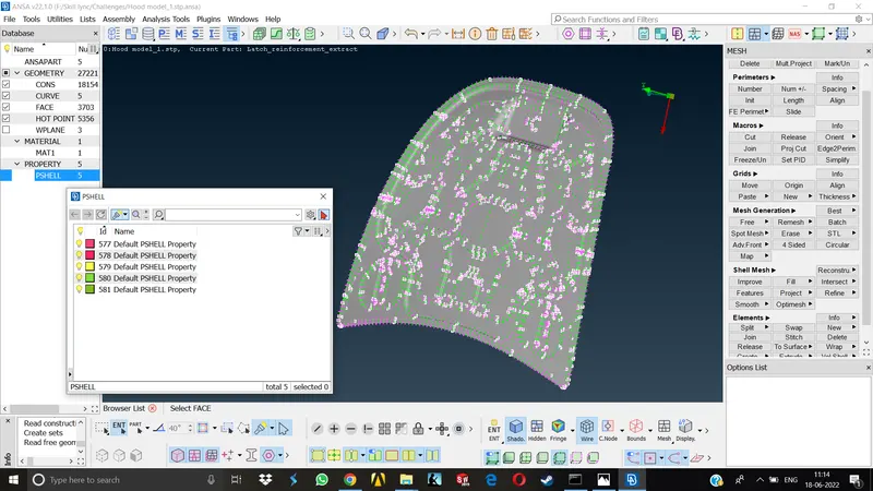
- The hood model is now visible, after going to the Database section by double clicking the Pshell tab, the different parts in the assembly can be seen.
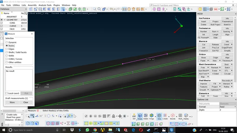
- Before performing any operation its always good to check the element length or distance between any two given nodes by going to the measurement>nodes.
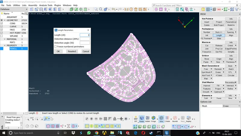
- To enhance the visual quality/avoid the distorted view and for the ease of doing further operations like faces cut, join etc, on the model we can go to the Mesh Module>Perimeters>Length then the selection window will open and then we can select the entities and assign a smaller length (1mm) for both Perimeter and Macros.
- Now we can check the geometry for errors by going to Toolbar>Checks>Geometry.
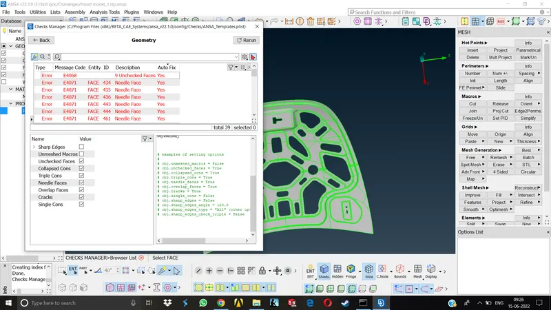
- We can see a lot of errors like unchecked faces and needle faces. As a beginner, I was told to deal with these errors manually , like by going to error>show only, one can see what actually the problem is and deal with it accordingly. Like deleting the unchecked faces and correcting the needle faces.
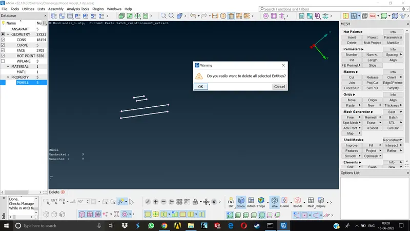
- Once we understood how to deal with the problem then its okay to perform Autofix by Right click>Fix on the errors.
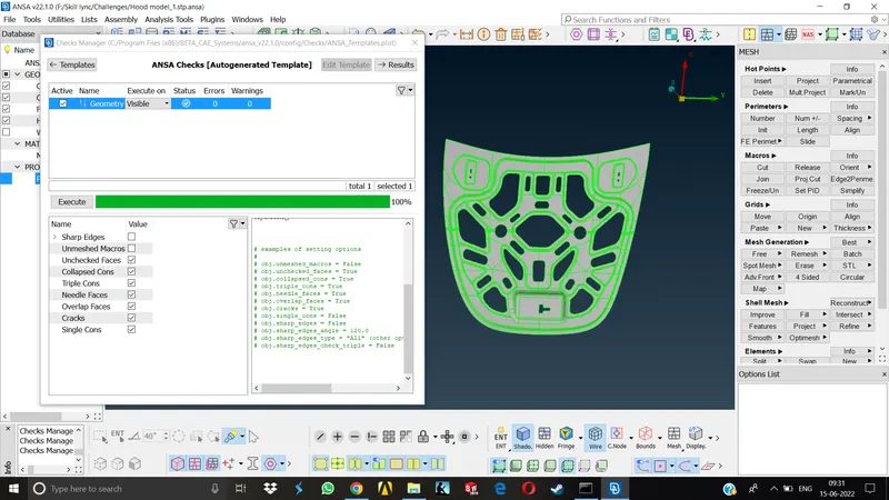
- After cleaning all the errors, one can perform a final geometry check to confirm if everything is okay.
Now, we can rename the parts according to the specifications and can keep visible only one part on screen which we will be working on by doing Right click>Show only or by switching on & off respective bulb icons in front of them. - Taking Midsurface- (Manual Mid)- First of all, Check for the overall thickness of the material by going to Measure tool and selecting any two nodes across the thickness of the part. In this case , it was 0.75mm for the inner extract of the hood.
- Now, go to Topo module>Faces>Offset , define a proper feature angle value at the bottom left area of the screen in order to select all the faces at once to save time,select the face , it wil turn white and for confirming, click the middle mouse button.
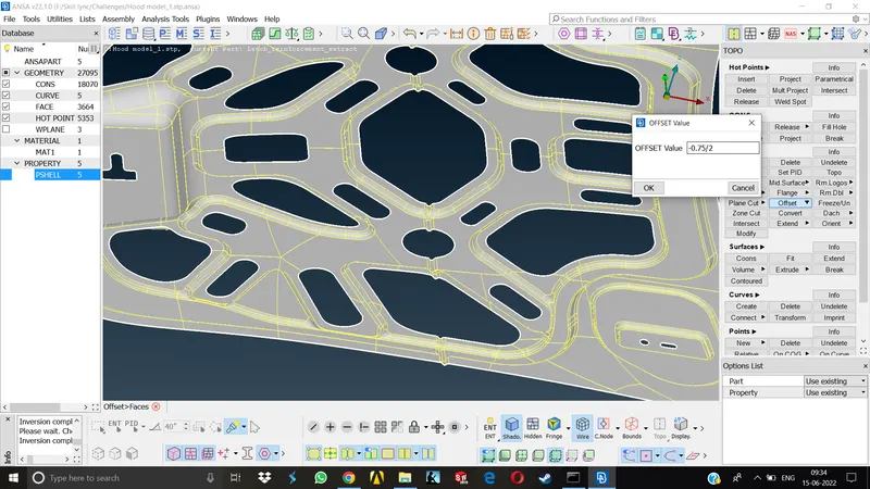
- After doing middle click, the arrow defining the direction of mid surface will be shown. Depending on the direction of this arrow we will have to give a offset value either +ve or -ve. Divide the thickness of the part by 2 and you will get the offset value for the midsurface. after entering the offset value and middle click, a window will pop up asking to keep the original faces or to delete them,in this case we are keeping the original faces.Now we have got our middle plane.
- Now once again we have to check the geometry for any errors and resolve them accordingly after performing topo on the Mid surface. It is very important to perform topo on mid for defining association with the neighbouring entities.
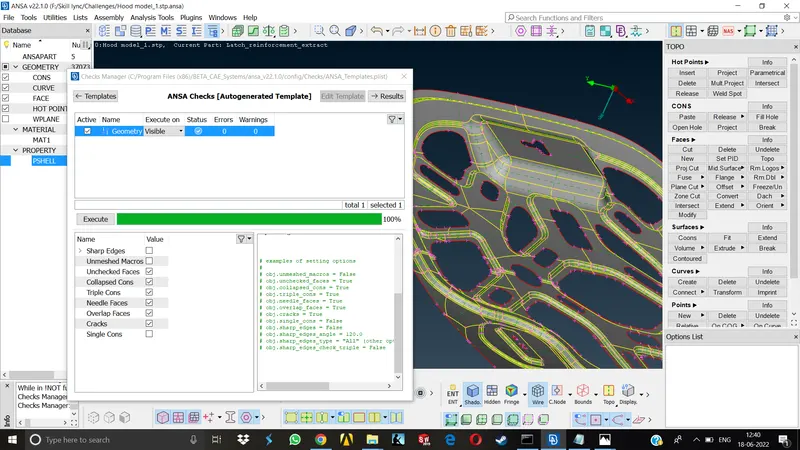
- Now, we can assign a new property card for the mid surface by Right click Pshell>New>Pshell. Rename the mid and assign a thickness equivalent to the parent surface. Now right click on this property card and select Apply option and select the mid surface and Middle click to assign this Pcard to the midsurface.We have generated a separate property card for mid.
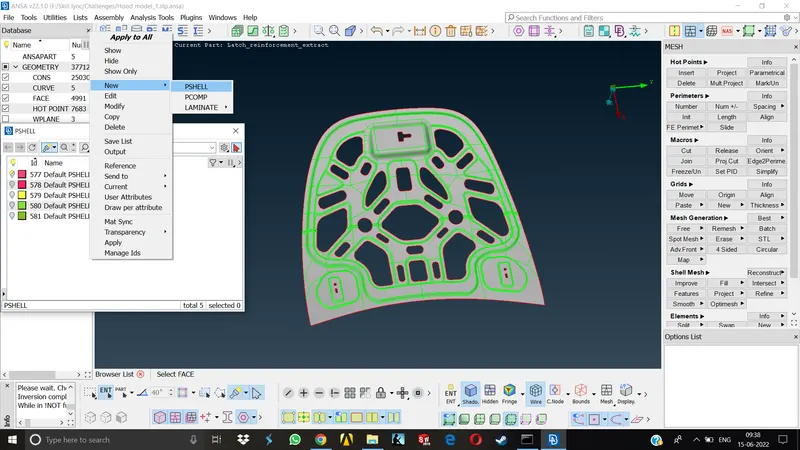
- Similarly we have to take the mid and assign new property cards to all the remaining parts.
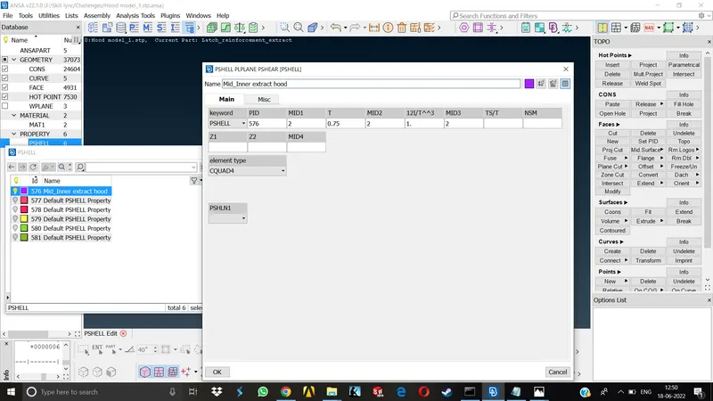
- MESHING- Once the mid is acquired, we have to set the Mesh & Quality parameters as per requirement.To do this select the property card of the part on which we have to perform mesh Right click>Show only.
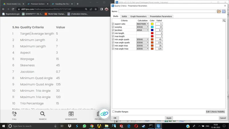
- The quality criteria and mesh parameters both can be accessed on the shortcut menu bar on top middle of the screen or going to Utilities menu. Simply by using the F11 shortcut key we can access the quality criteria tab and change the settings as per requirements. After entering all the values click Apply>Ok.
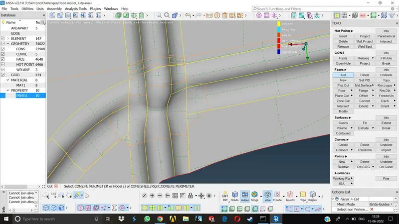
- Now, we have to check the elements if they are ok as per quality. This is done by manually measuring the element lengths in complicated areas. if they are failing, we have to perform various operations like Cut Faces or Macros, remove all the construction lines , remove the feature lines which are too close to each other or which may disrupt the meash flow.It is always important to make all the feature lines smooth and remove the unnecessary ones before we start to mesh like it is shown above.
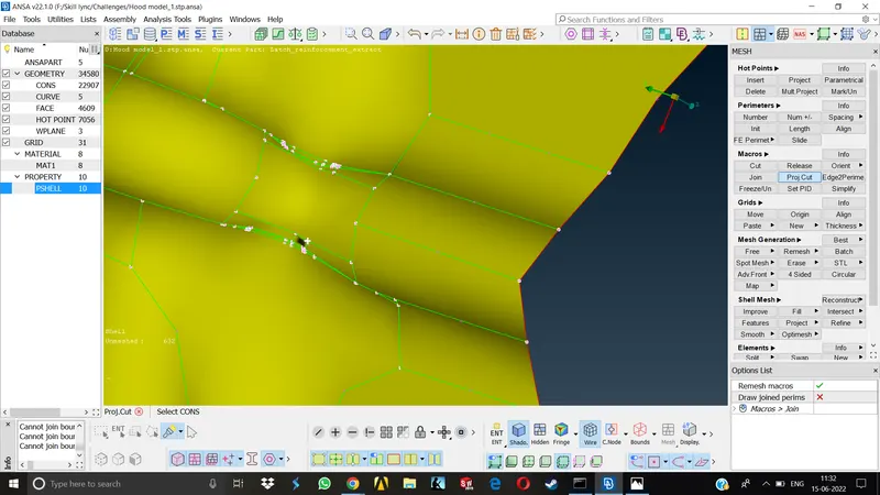
- Next step is going to the feature areas and check if the no. of nodes are even.for eg if there is a circle we have to check,go to Perimeters>Numbers click on the circle a window will show you the no of nodes. if its even, all good if not, we can change it by entering any even no. > Apply.
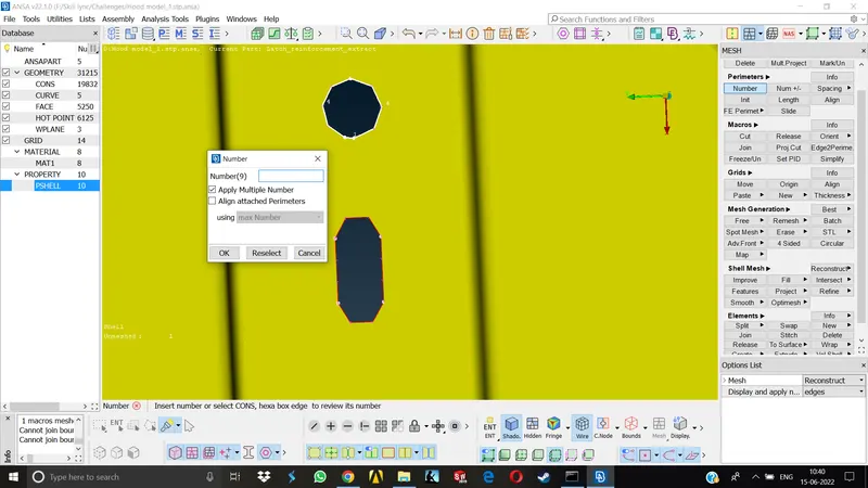
- It is also recommended to slide the circles or any feature holes parallel to the adjecent surface or entities to get a better mesh flow.
- Now if the surface is big enough we can divide it into no. of squares or rectangular entities. We can also draw lines from circle or any feature area to adjecent area to avoid tria elements. This is done by using Macros>Cut command. But we have to join these macros after the mesh is generated.
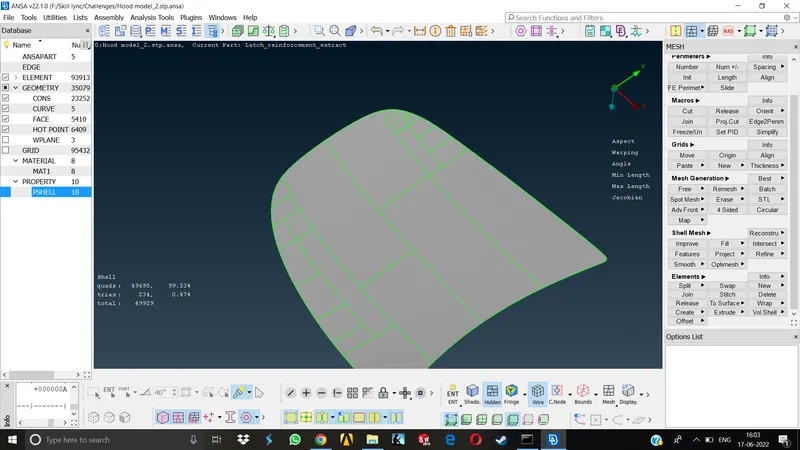
- once everything becomes smooth, check the mesh parameters if they are as per requirement go to Mesh parameters>Basic >Target length,min length,max length. Here we are keeping the mesh type General,Mixed and First order as it is.NOw we can start to mesh.
- Go to the Mesh module>Mesh Generation>Best. We can also use Free mesh , Spot mesh command.The goal is to get best mesh results irrespective of the commands.
- Start meshing from the areas which are complicated and move to easier areas.After meshing any region we have to check for the mesh quality. In order to do this we have to keep the Hidden mode on.
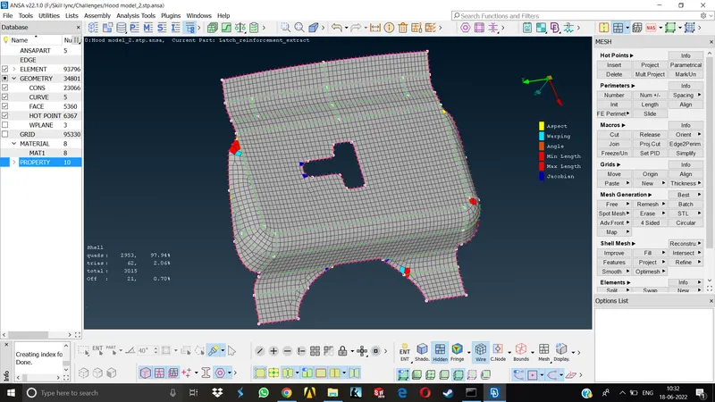
- Each quality defect has its own color which can be seen in the adjecent window, also the unmeshed areas, no of quads, trias, tria percentage and off elements can also be seen on the another adjecent window. The off elements represents the areas which are failing for quality.
- To resolve these off elements primarily we have to use various commands like Improve , Reconstruct, Smooth under Elements tab . if it persists further,depending upon the type of error we have to use different commands Eg. sometimes we need to spilt the elements, increase/decrease the no. of nodes on the perimeter, paste nodes etc. No matter which commands you use, the goal is to obtain a smooth mesh flow with min Tria elements.
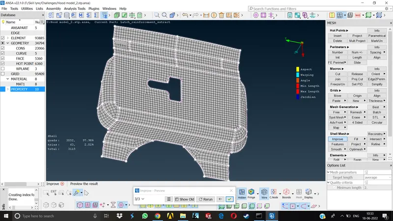
- We also need to eliminate as much tria elements as possible. For this we can use various commands like Split, join, swap or paste nodes. we can also determine the parametric paste positions.
- We can use these similar steps to mesh all the remaining parts. After meshing is done, go to Quality criteria >Presentation parameters>Draw shell as solid .
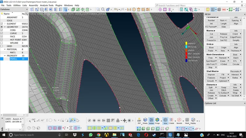
- FE model with applying thickness
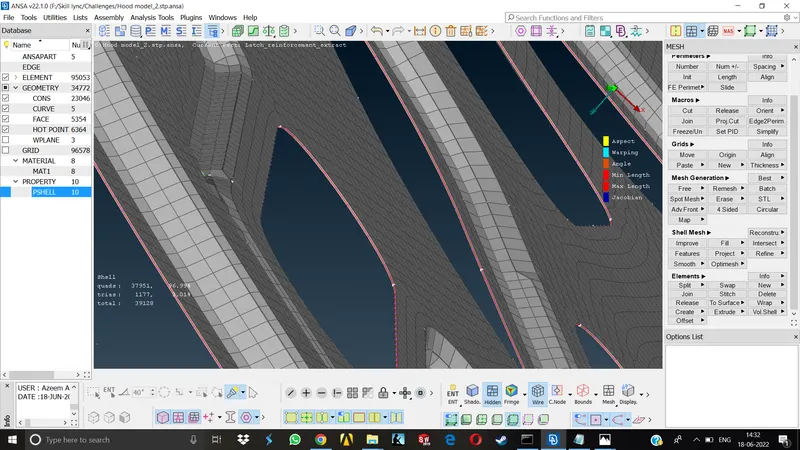
- Without thickness
LEARNING OUTCOMES-
As this was the first challenge in this course, pretty much everything was new to me. I made sure that i learnt all the basic commands and procedures by repeating them, practicing them. To mention specifically,
- Cleaning up the geometry
- Manual mid surfacing
- Refining &Setting up the existing surface for a good mesh quality
- Dealing with the Quality parameters and fixing the off quality elements by using basic commands.
- Using various practices discussed in the teaching videos to obtain a better mesh.
Conclusion-
I can say that i have learnt to use most of the basic commands generally used for cleaning geometries, taking midsurfaces , performing meshing operation etc and i have tried my best to complete this challenge as per the required parameters. The Geometry cleanup, Mid surfacing , Meshing of all the parts given in the challenge has been done as per the given quality parameters.
NOTE - As im unable to upload the model to the skill lync website due to some isssues, I am told by a support engineer to share a google drive link of the model here in the report.
Google drive link for the model- https://drive.google.com/file/d/1CS_3IAn06WxrbXOHxc_idiZRqlfNIjFH/view?usp=sharing