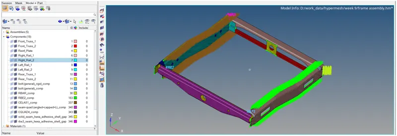
Week 9-Creation of 1D Connectors Challenge
Report
AIM:
For this challenge, you will have to mesh the given geometry. Provided below are the quality parameters that you have to follow.Create connector and Attach the various parts of the given model.
Procedure:
following step to be done for meshing the given Frame Assembly.
1] Import Geometry:
import the geometry in the .stl,.STEP,.IGES format. import > import geometry > Choose the File and hit on open.
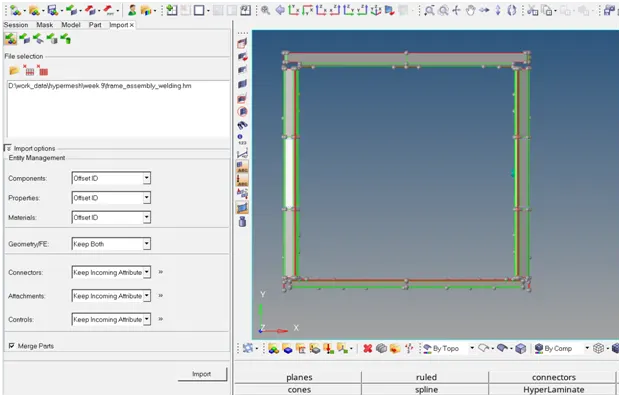
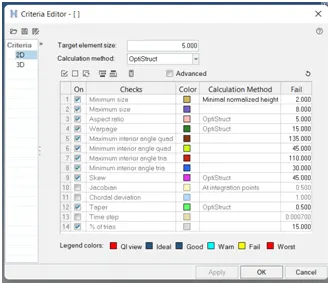
2] assign the Quality Criteria :
preferences > criteria file setting >put the proper value
3] geometry clean-up:
by using the sum of this command we clear the geometry
geometry > surface > ruled/spline
geometry > surface edit > trim/extend
geometry > quick edit panel
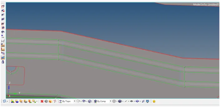
4] visualization panel:
from visualization panel we check the free edge are present in the geometry,if any free edge are present then remove this free edge.
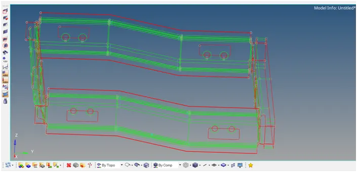
5] creating the mesh:
creating the mesh on the mid-surface by using automesh.here we use the element size is 5 mm and element type is mixed type.
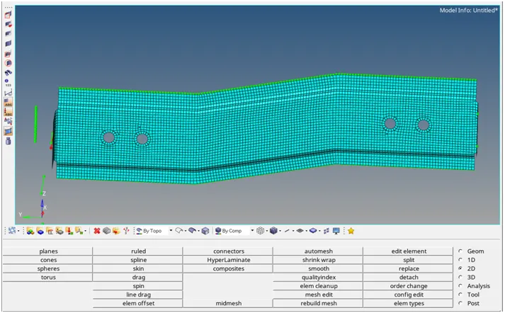
6] checking for quality criteria:
by using the quality index option we check the quality of mesh and also clear the quality.
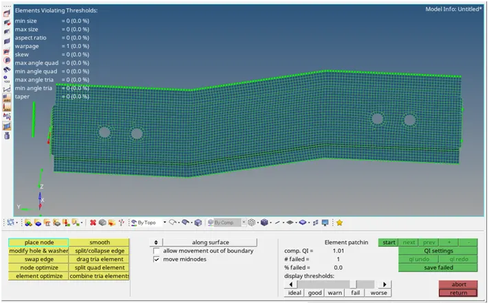
7] providing the connection:
1. Right_Rail_2 & Front_truss_1:- Seam-Quad(angled+capped+L)
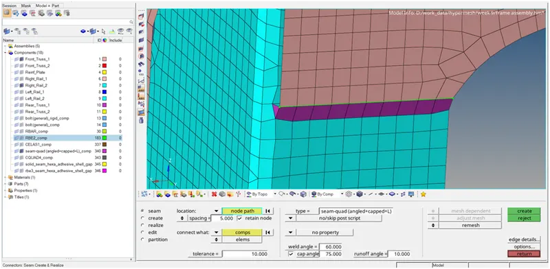
2. Left_Rail_2 & Front_truss_1:- Quad elements
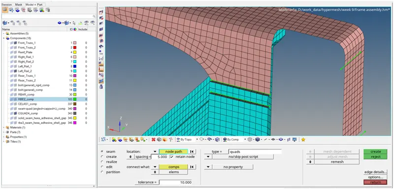
3. Front_truss_2, Front_truss_1 & Right_Rail_1:- Spot weld with 2 Layers and 5 mm Diameter
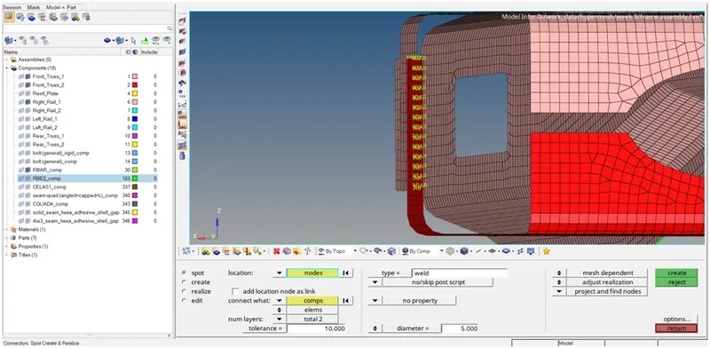
4. Front_truss_2, Front_truss_1 & Left_Rail_1:- Hexa (Adhesive)
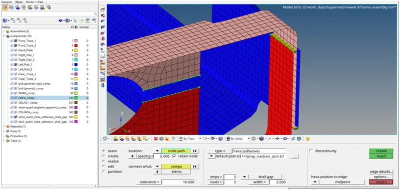
5. Rear_truss_2 & Right_Rail_2:- Bolt Connector
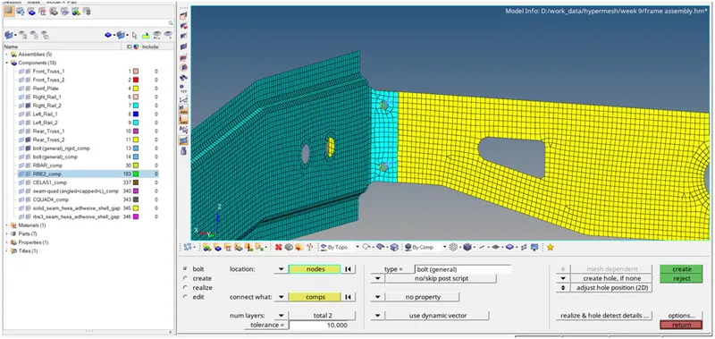
6. Rear_truss_2 & Left_Rail_2:- Bolt Connector
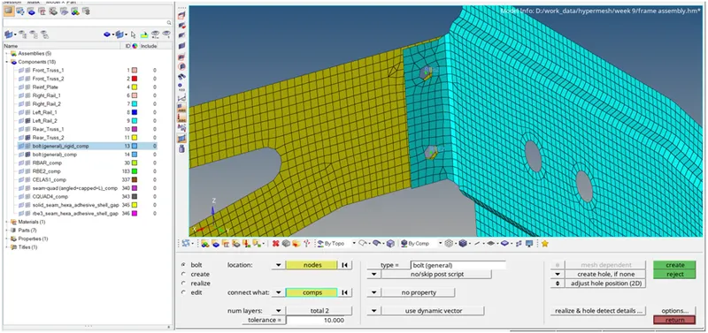
7. Right_Rail_1 & Right_Rail_2:- Spot-weld with Rigid Elements
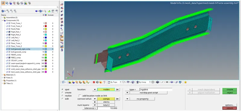
8. Left_Rail_1 & Left_Rail_2:- Spot-weld with Spring Elements
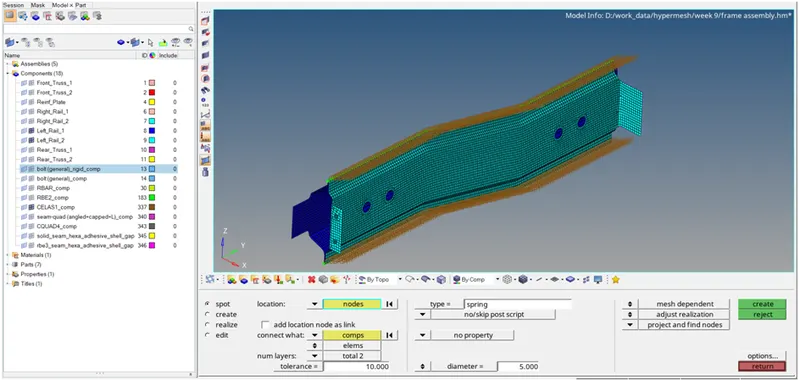
final product: