Week 9-Creation of 1D Connectors Challenge
WEEK-9
STEPS:
- Import model into hypermesh.
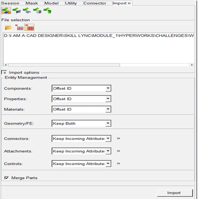
- After import hide all components other than “front truss 1”.
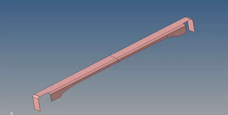
- Press F12 for meshing.
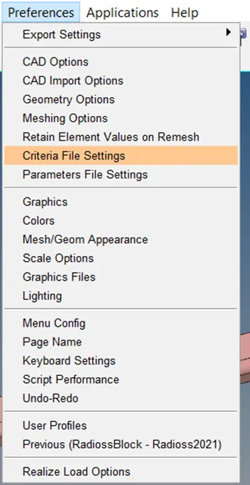
- But before that go to preferences in main menu and select criteria file settings.
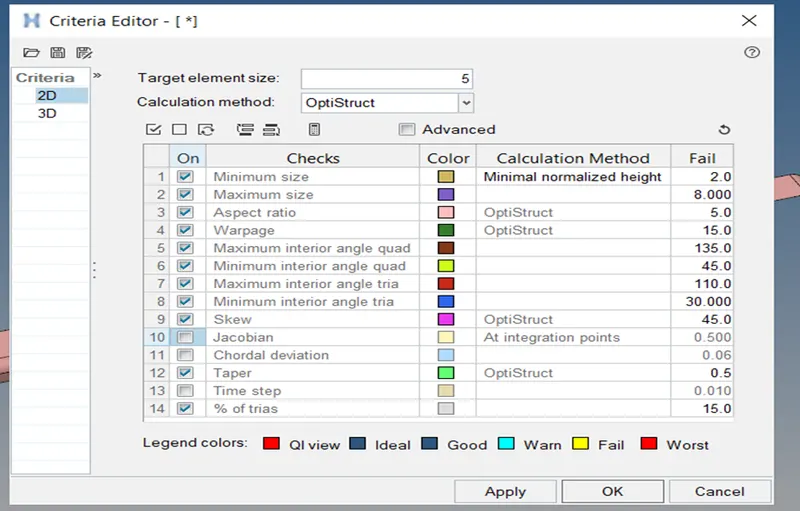
- Set quality criteria as shown in image and as given in question.
- As this component looks symmetrical, for the ease of mesh, delete half of the component as shown in image..
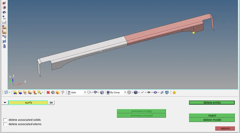
- Created a node(for node creation, go to geom, select temp node or press shift+F2 and click on the corner point as shown in image.) and splitted the surface as shown in image for ease of meshing.
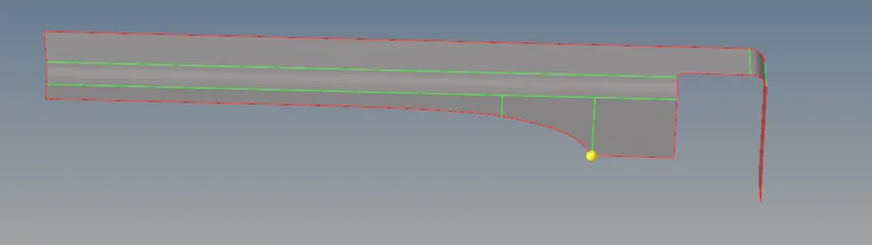
- Now press F12 and go quad mesh and before that make current component as “front truss 1”

- Do meshing by selecting single surface at a time. Do it surface by surface, one after one.
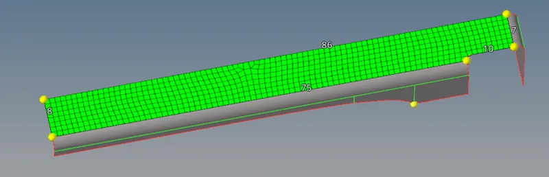
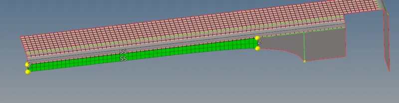
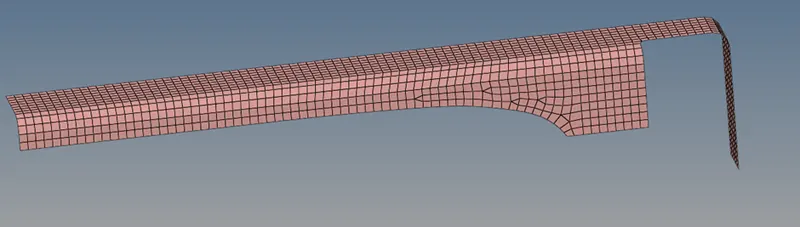
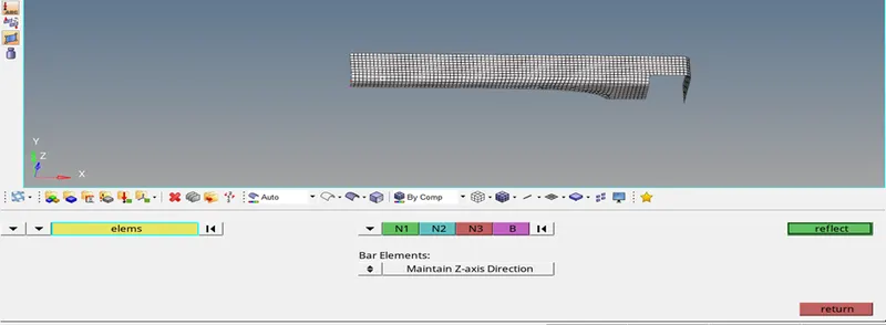
- Now go to tools, select reflect, select displayed elements, duplicate it, assign n1,n2,n3 and base and click on reflect.
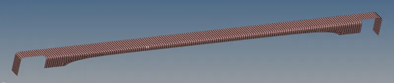
- Check for quality criteria by going to 2D and quality index.
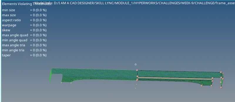
- Check for nodes connectivity by going to tools and selecting edges. Click on preview equivalance.
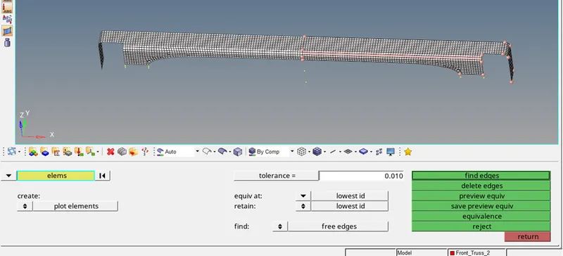
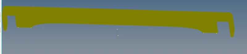
- it shows all nodes are not connected to each other, so click on equivalence. And done.
- Now unhide the second component named “front truss 2”.
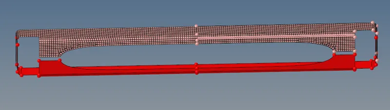
- As you can see, this component is also same as above but in opposite direction, except the end filleted portion.
- So lets reflect the mesh generated in component 1 named “front truss 1” about y axis.
- For that lets create some nodes for base point for reflect command.
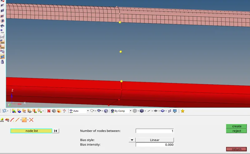
- For that go to geom, select nodes, use interpolate nodes to create a mid node between two nodes that are selected as shown in image.
- Now again go to tool, and use reflect tools to reflect the mesh, but before that make the “front truss 2” as current component by right clicking on the component and slect make current .
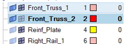

- Use current component in this option and reflect in z axis direction.
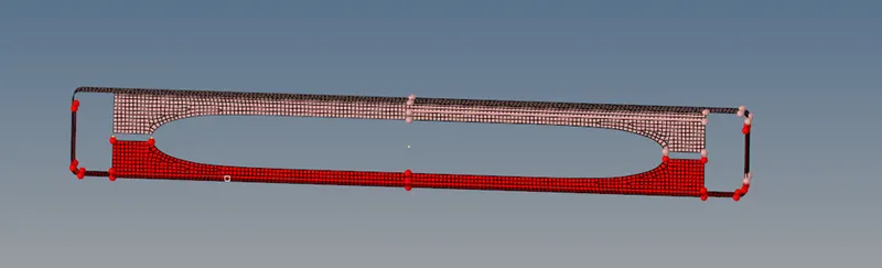
- As you can see below, the elements are not on the surface, so lets use project elements from tools.
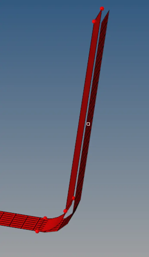
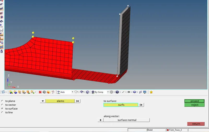
- Select to surface, select elements as shown in black color in image, select surface as shown in white color in image, set along vector to surface normal and click project.
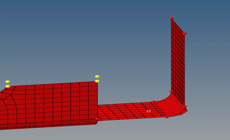
- It will look like this. Do same procedure again for remaining elements.
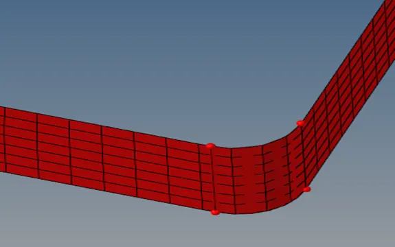
- As you can see, the elements are not anchored with feature line, so use project nodes this time and line.
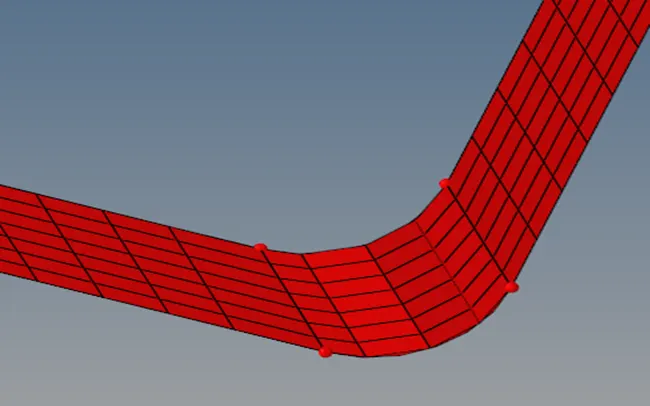
- Repeat step 11, 12 and 13 for quality check and equivalence.
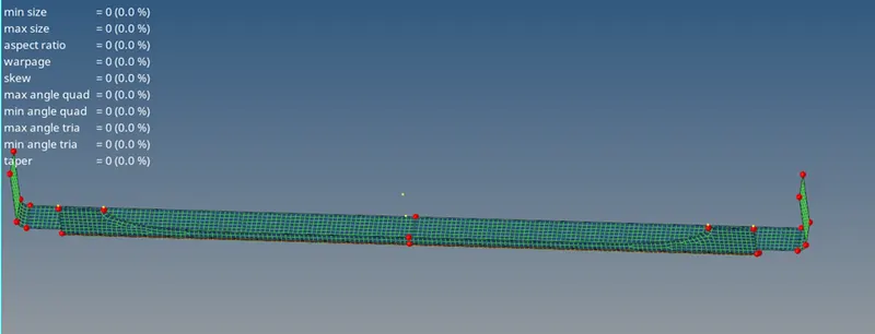
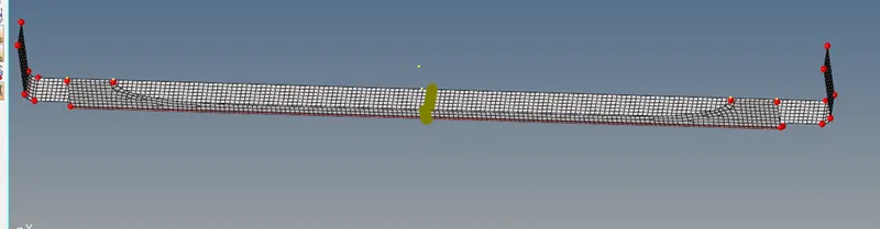
- Now make component named “reinf plate” as current component and do meshing on it.
- Unhide this component and hide all other.
- Use F2 to delete one-forth surface as its symmertical.
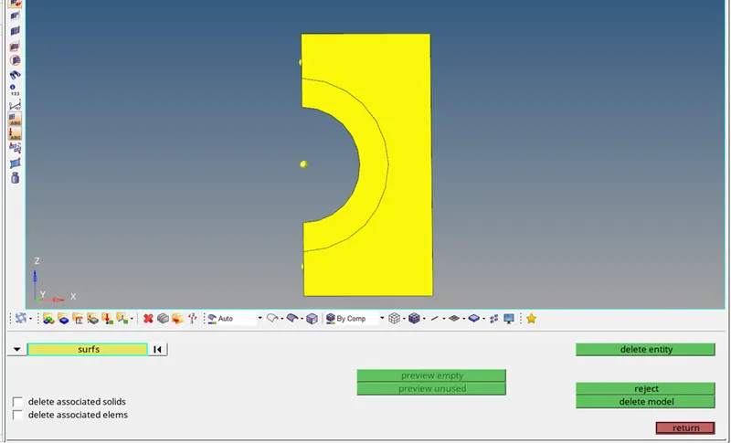
- Create node on circular edge by using nodes from geom.
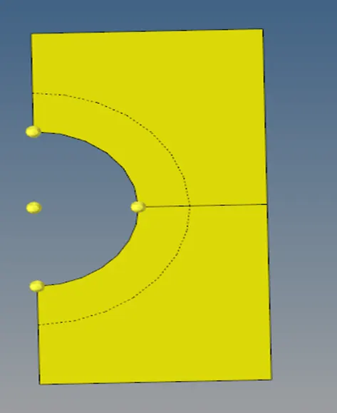
- Press F11 and use split surf line by selecting node and straight edge on right hand side.
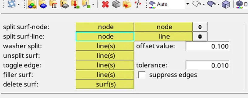
- Then use delete surf from same option and delete one of the surface.
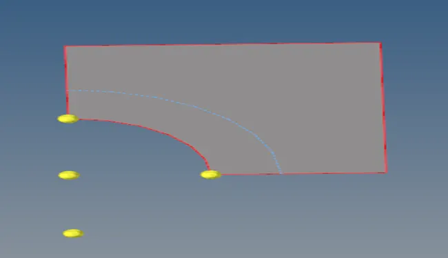
- Press F12 for meshing.
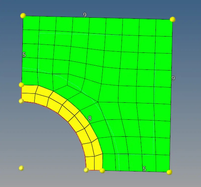
- Repeat step 10 for reflecting the mesh in x and z axis.
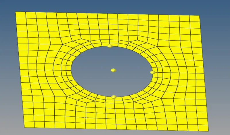
- Check for mesh connectivity (same as step 12) and click on equivalence.
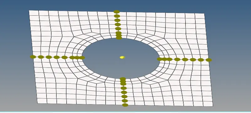
- All done for this component.
- Repeat the procedure for next component named “right rail 1”
- Unhide it and hide all other components.
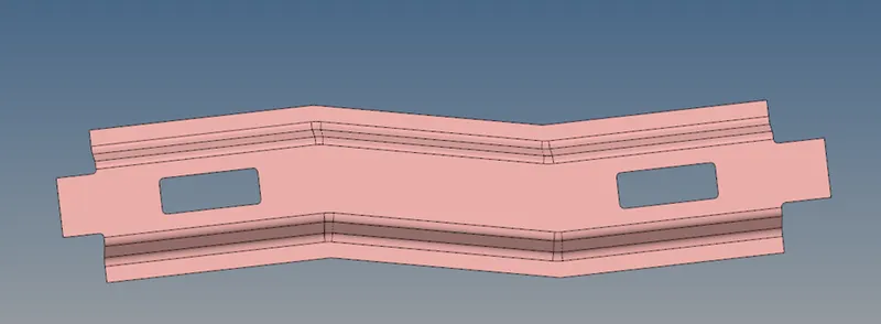
- Make current component as this component.
- Press f11 and check for geometry.
- No geometry repair required.
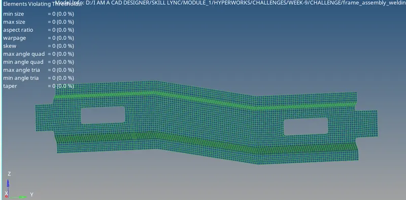
- Press F12 for mesh and start meshing one after one surface.

- After meshing and checking for quality criteria, this is the result.
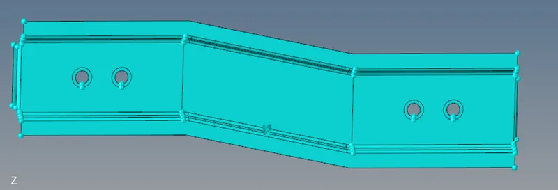
- Follow same procedure from step 39 to 44 for new component named “right rail 2”.
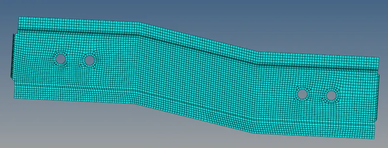
- After meshing.
- Moving forward to next component that is “left rail 1, it the exact mirror of “right rain 1 ” component and same goes for “left rail 2”.
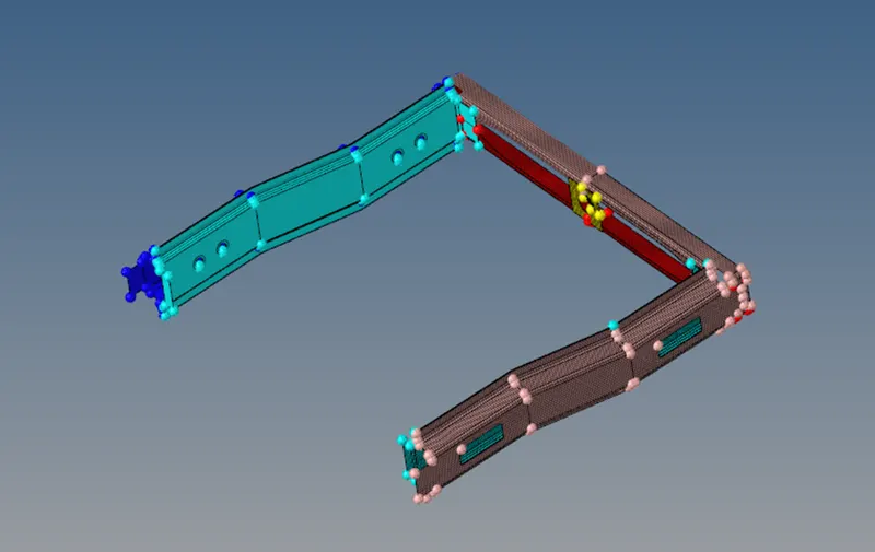
- So, just use reflect option from tools.
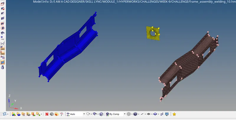
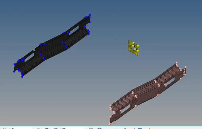
- After selecting base node as the yellow node on circle as shown in image. This is the result.
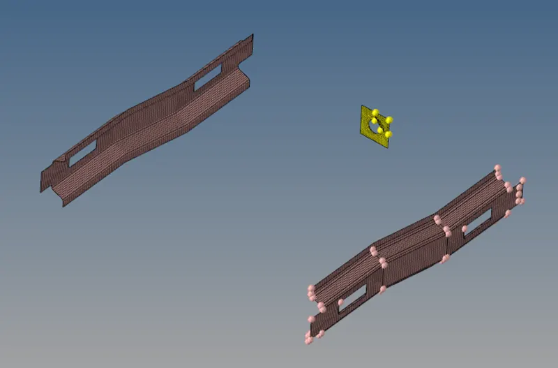
- As you can see the “left rail 1” mesh is in “right rail 1”, so to move “left rail 1” mesh to its original component.
- Go to tools, organize, select element, set destination component to left rail 1 and click on move.

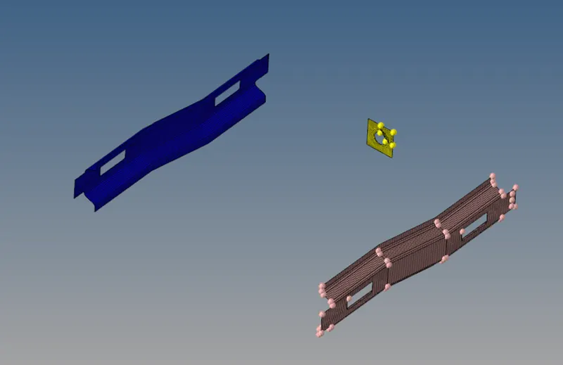
- Do same procedure for “left rail 2”. Follow from step 48 to 52 again.
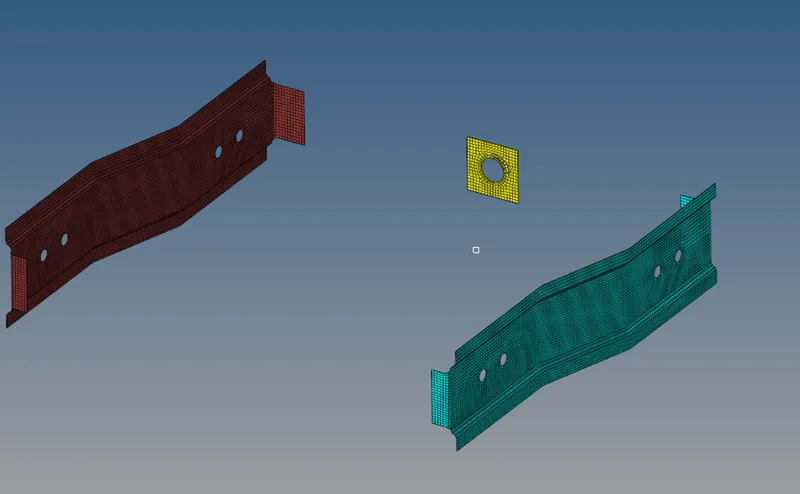
- Hide all component and unhide a new component named “rear truss 1”.
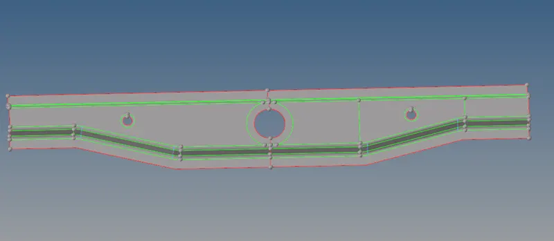
- Delete half of the geometry, as its symmetrical, and clean up the geometry.
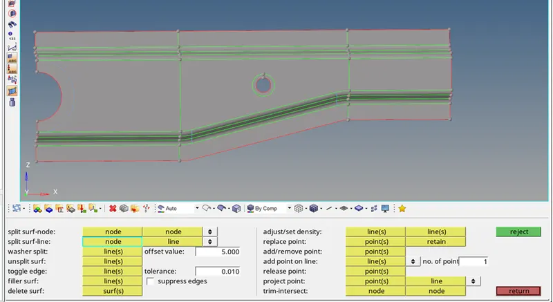
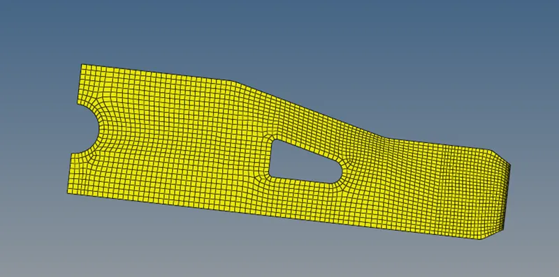
- Now do meshing by pressing F12.
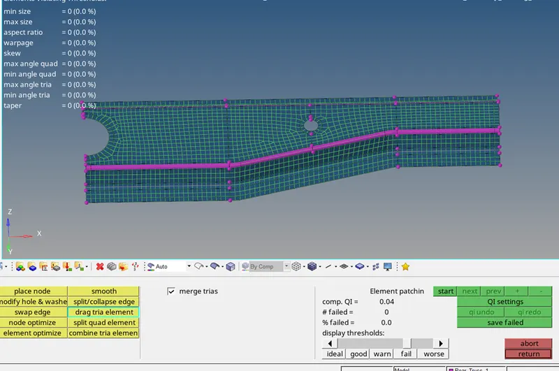
- Repeat step 10 for reflect.

- Repeat step 12
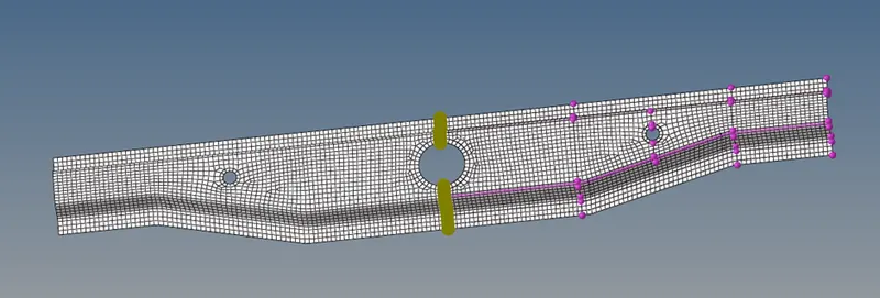
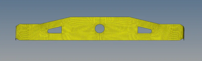
- Rear truss 1 completed.
- Moving forward, next component “rear truss 2”
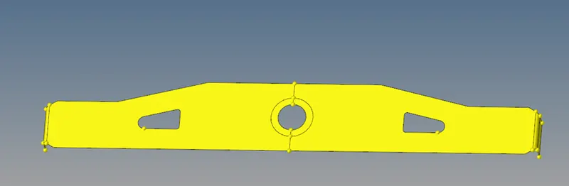
- Repeat step 55.
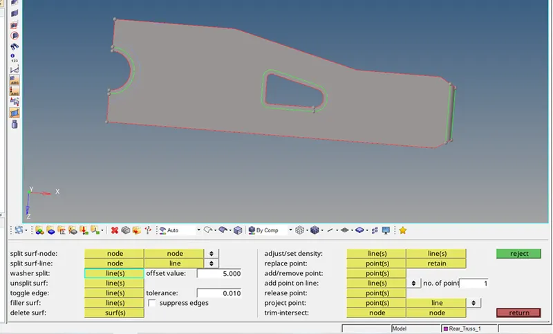
- Repeat step 56
- Repeat step 57
- Repeat step 58
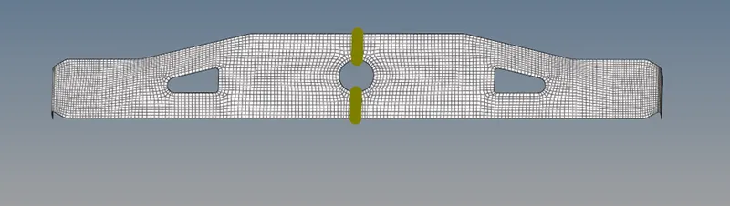
- This component is also done.
- Moving forward, next component “front truss 1.1”.
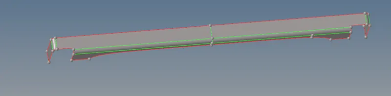
- Repeat step 55.
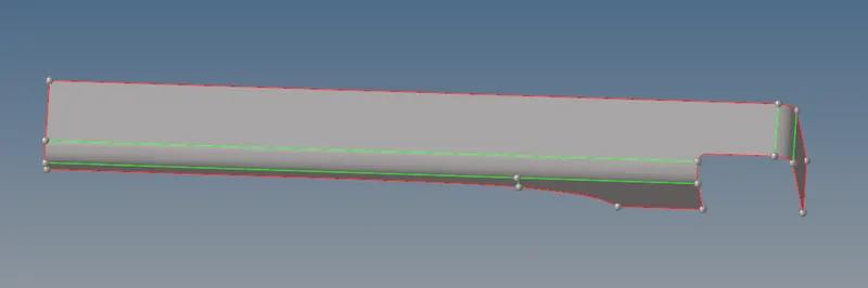
- Repeat step 56.
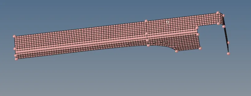
- Repeat step 57.
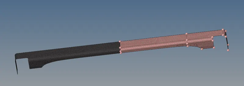
- Repeat step 58.
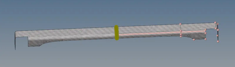
- Front truss 1.1
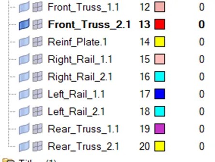
- All the components including front truss 1.1 to rear truss 2.1, so delete all these components.
STEPS:
Right_Rail_2 & Front_truss_1:- Seam-Quad(angled+capped+L)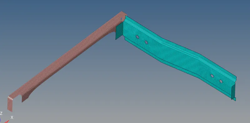
- Connectors are available in 1D,2D and 3D panel.
- Go to 2D panel, select connectors.

- This panel will open.

- Click on seam. This panel will open.

- Select type: as seam-quad (angled-capped-L)

- Select node list from location option.

- Set tolerance more than 3, because the gap between two components is exact 3, As shown in image.
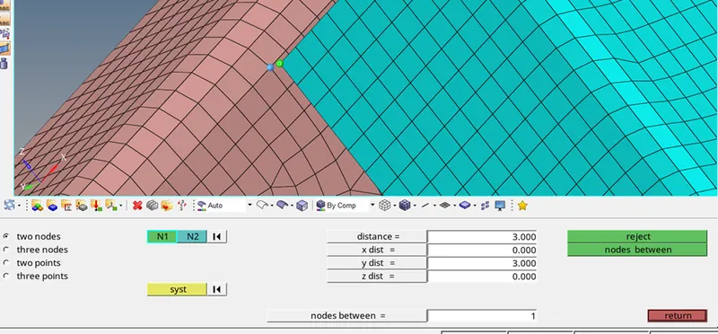
- Set spacing as 5.
- Select nodelist, and select nodes from screen. And click on create.
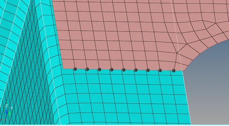
- This is the result.
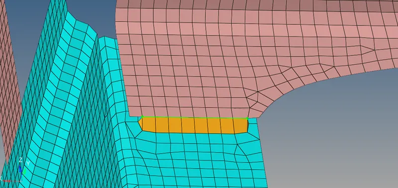
- The green line of seam weld shows that it is realised.
- The mesh got distorted, so it has to be fixed.
- After fixing it, it looks like this.
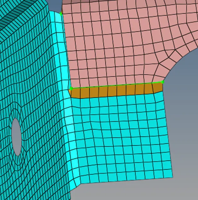
Left rail 2 and front truss 1 :- Quad elements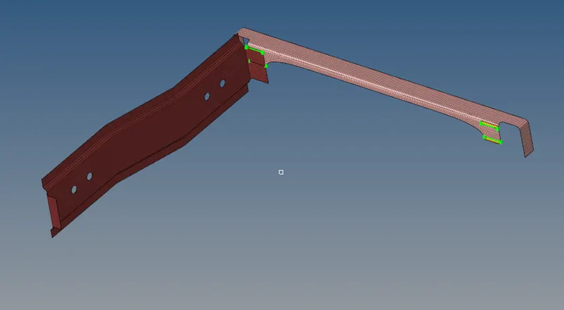
1.Go to 2D panel, select connectors.
- This panel will open.
- Click on seam. This panel will open.
- Select type: as quads
- Select node list from location option.

- After clicking on create, this is the result.
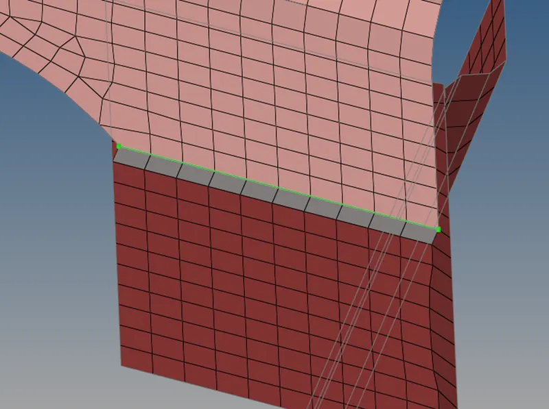
- Do this on other side.

Front truss 2,front truss 1 and right rail 1 :- Spot weld with 2 layers and 5 mm diameter.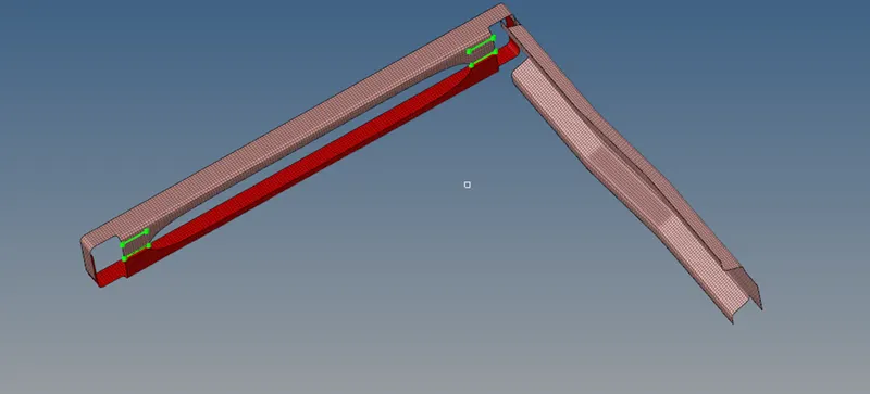 1. Go to 2D panel, select connectors.2. This panel will open.
- Click on spot. This panel will open.

- Select type: as weld
- Select node list from location option.
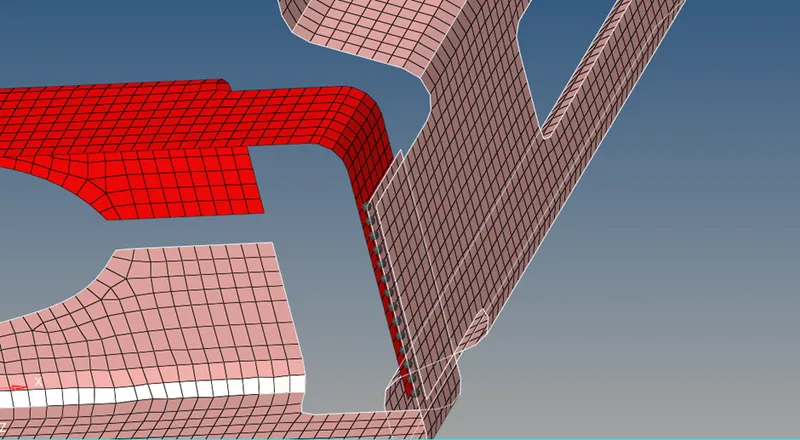
- Select components, set layers to 2 and dia to 5mm.
- Set tolerance to 3.5. and click on create.
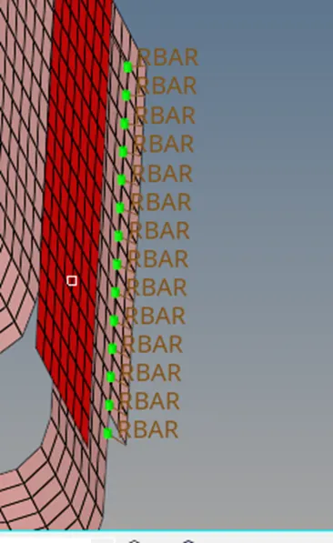
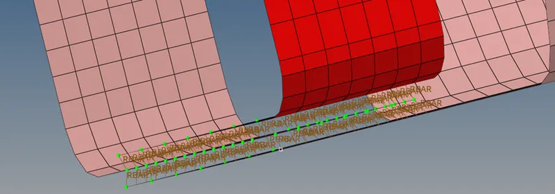
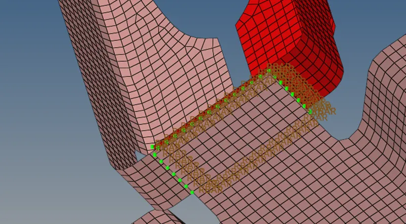
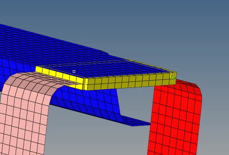
Front truss 2,front truss 1 and left rail 1 :- hexa (Adhesive)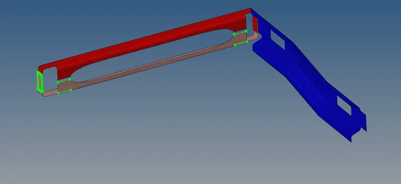 1. Go to 2D panel, select connectors.
2.This panel will open.
3. Click on seam. This panel will open.
- Select type: as hexa (adhesive).

- Select node list from location.

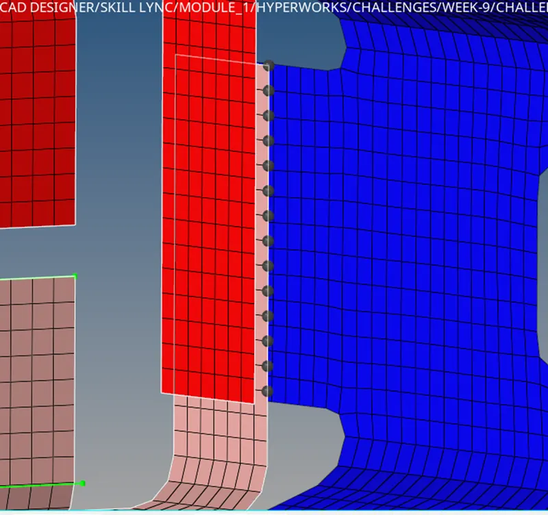
- Select components, set width to 3.5 and click on create.
Rear_truss_2 & Right_Rail_2:- Bolt Connector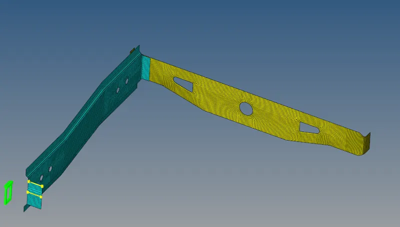 1. Go to 2D panel, select connectors.
2. This panel will open.
3.Click on bolt. This panel will open.
4.Set tolerance to 4 and type as bolt(general), set create hole if none.
- Select node and components and click on create.
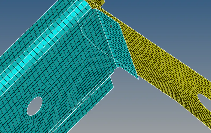
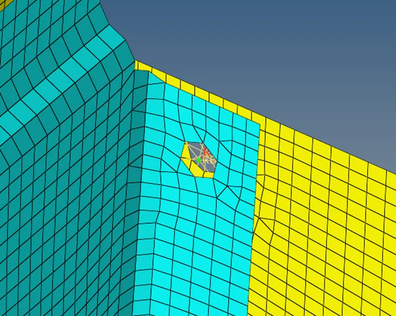
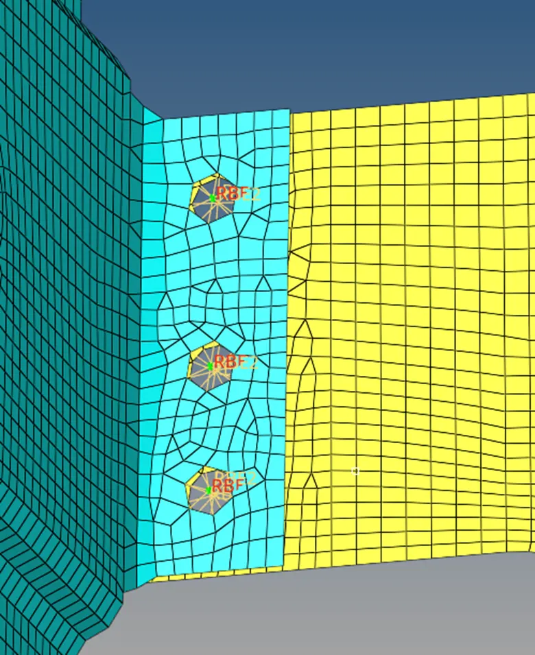
- This is the result.
- Remeshing the area beside the bolt connector.
Rear_truss_2 & left_Rail_2:- Bolt Connector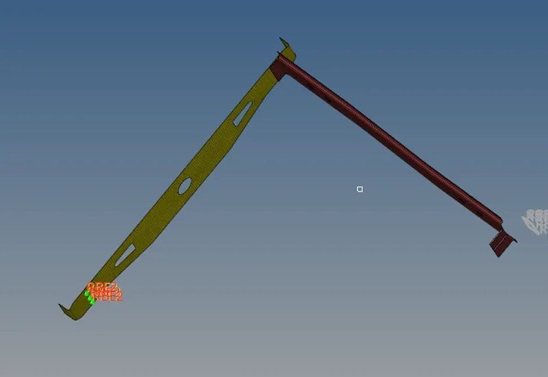 1. Go to 2D panel, select connectors.
2. This panel will open.
3. Click on bolt. This panel will open.
4.Set tolerance to 4 and type as bolt(general), set create hole if none.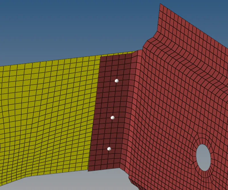
5.This is the result.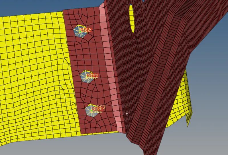
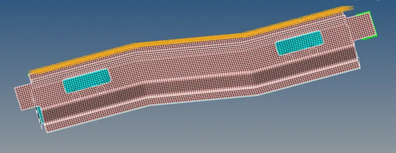
Right_Rail_1 & Right_Rail_2:- Spot-weld with Rigid Elements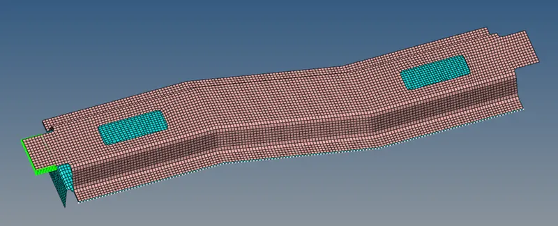
1. Go to 2D panel, select connectors.
2. This panel will open.
3.Click on spot. This panel will open.
4.select nodes, set type as rigid, tolerance 4, diameter 5, select components.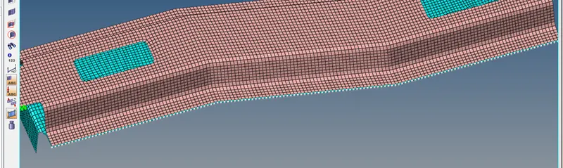
5.click on create.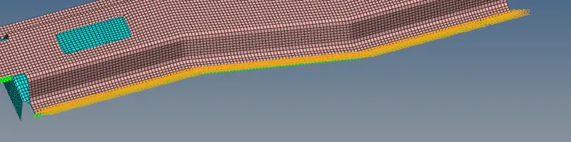
- do it on other side also.
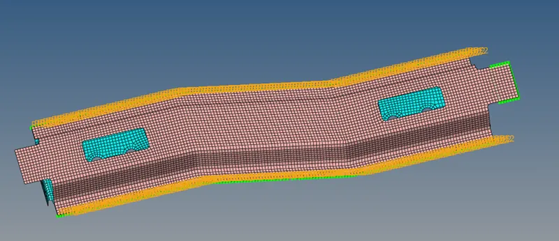
Left_Rail_1 & Left_Rail_2:- Spot-weld withSpring Elements 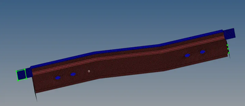 1. Go to 2D panel, select connectors.2.This panel will open.
3. Click on spot.This panel will open. 4.select nodes, set type as spring, tolerance 4, diameter 5, select components.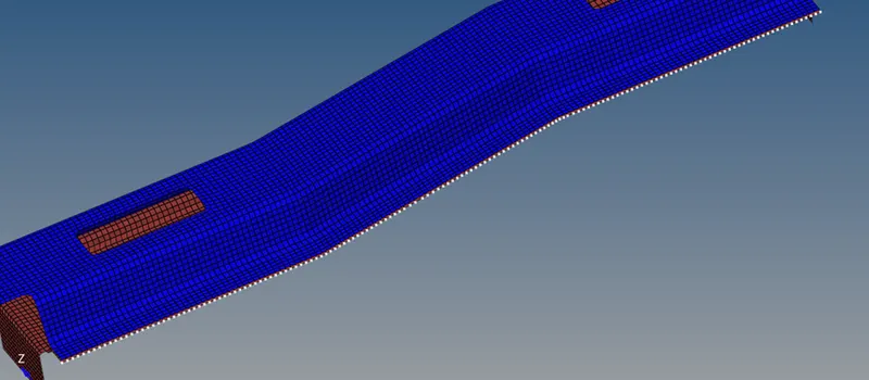
5.click on create.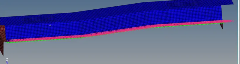
6.do same process on other side.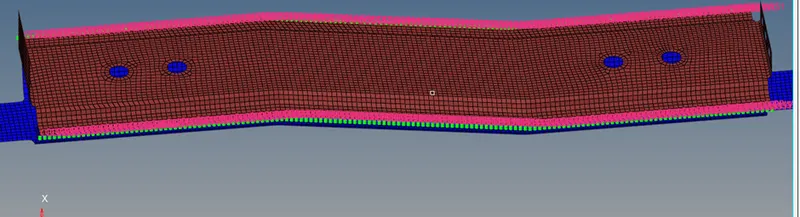
Rest all the component left Join them with suitable connectors:
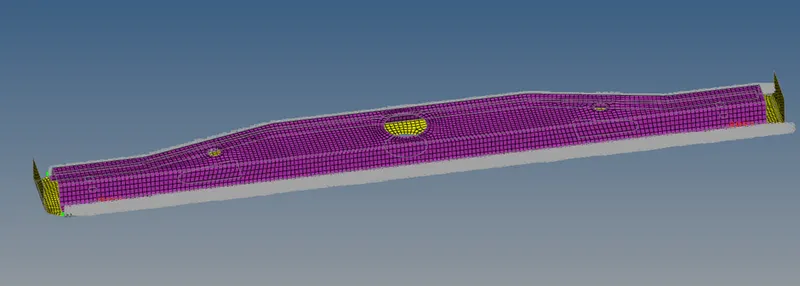
i) seam weld- type hexa (adhesive), between rear_truss_1 and rear_truss_2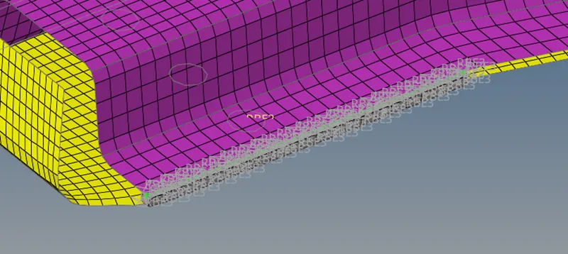
 ii) right rail 1and rear truss 2, spot weld, type: weld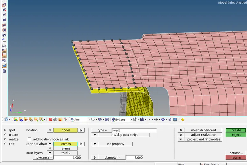
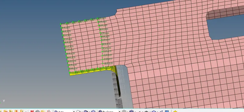
iii) right rail 1and right rail 2, bolt, type: bolt (general).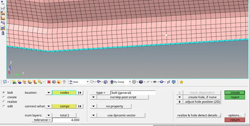
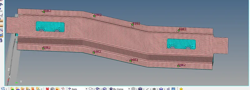
iv)left rail 2 and front truss 2,seam , type: quad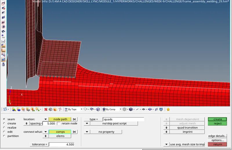
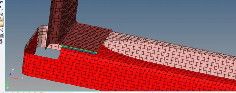
v) right rail 2 and front truss 2,seam , type: Seam-Quad(angled+capped+L)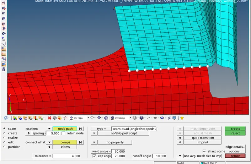

vi) front truss 2 and reinf plate, seam connector, type: Seam-Quad(angled+capped+L)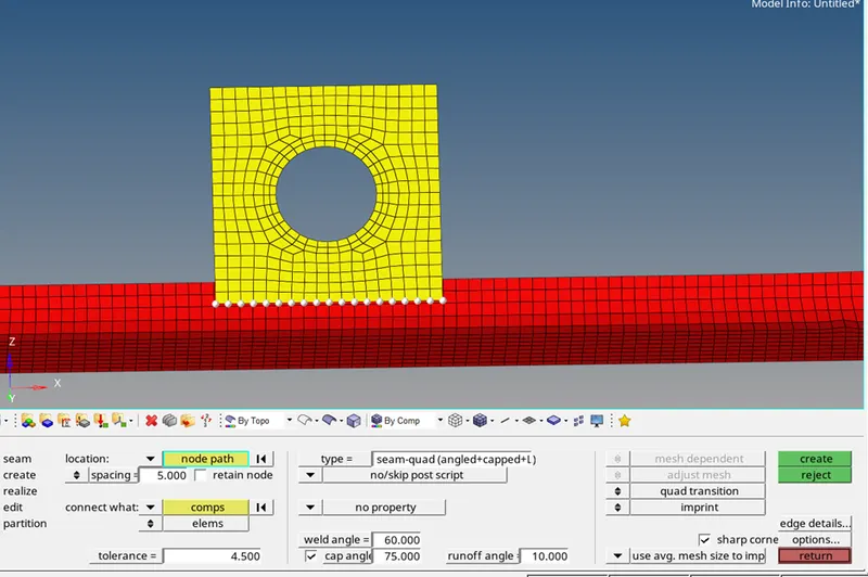
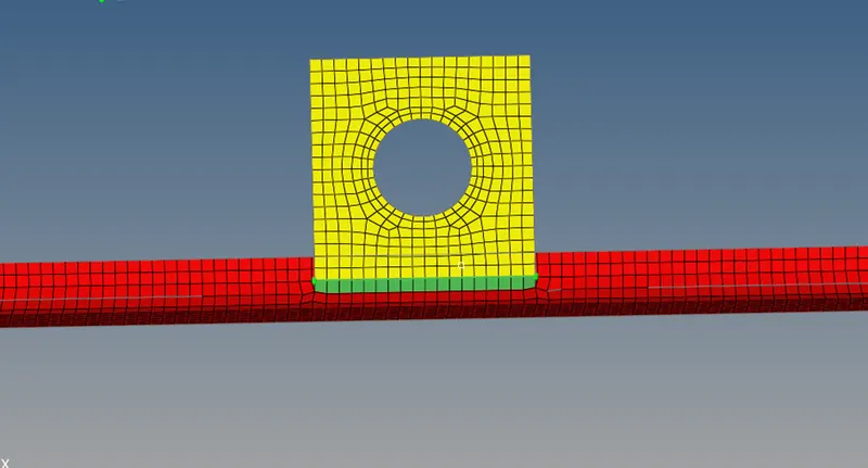
vii) front truss 1 and reinf plate, seam connector, type: Seam-Quad(angled+capped+L) 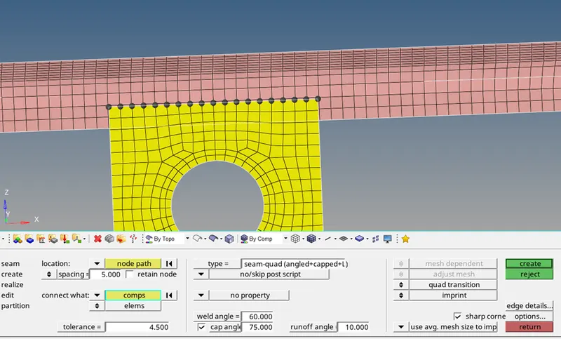
CONCLUSION:
- UNDERSTANDING THE CONCEPT OF USING CONNECTORS.
- AFTER APPLYING CONNECTORS, MESH GETS DISTORTS, SO REMESH HAS TO BE DONE, FOR PROPER MESH FLOW.
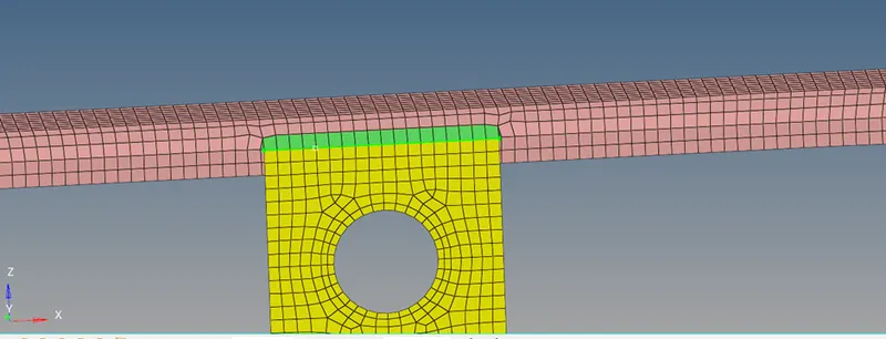
NOTE: ALTHOUGH IMAGES SHOWN ABOVE HAVE BAD QUALITY MESH, BUT I HAVE MADE IT INTO BETTER QUALITY IN THE HYPERMESH FILE