1D Element Creation in HyperMesh
Ques:1 mesh the given component with the size of 5 units.
Ans: Steps:
- Import the model first.
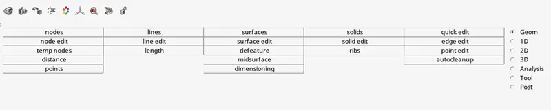
- Go to Geom from main menu page.
- Select midsurface from main menu bar.
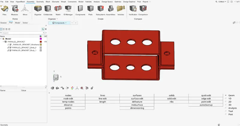
- Do surface extraction as this model has uniform thickness throughout so, shell mesh will be best.
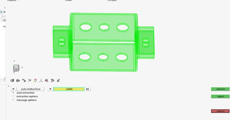
- Select both solids and click on extract.
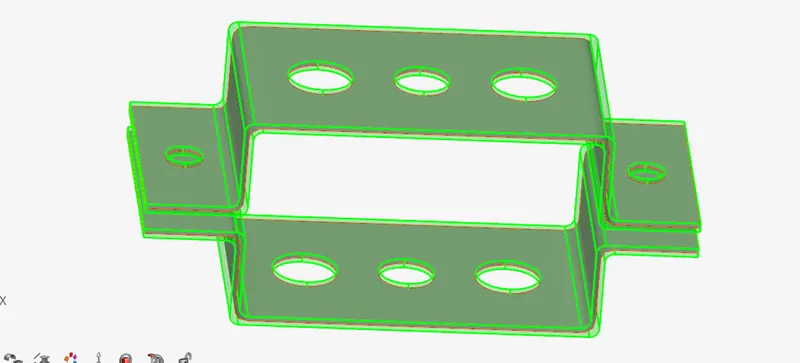
- It will look like this.
- Go to tools and select delete, to delete the solid bodies/components.
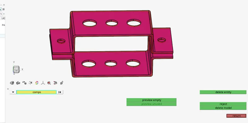
- click on components on screen and click on delete.
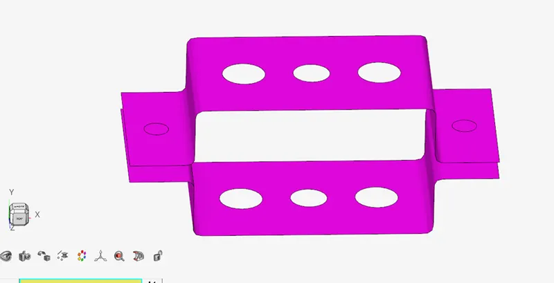
- It will look like this.
- Now create a new component for individual bodies or components displayed on screen and move them in it because both the surface extracted are in single component which is not preferable.
- To create a new component, right click on model in tab bar.
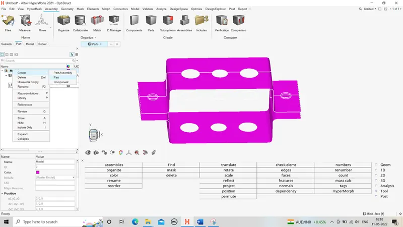
- Select component.
- A new component will be added, rename it as “bracket 2” and rename the first generated mid surface component as “bracket 1”.
- To do renaming of any component, just right click on the component in tab bar and select rename.
- Now move second component into bracket 2.
- To do so go to tools in main menu page and select “organize”
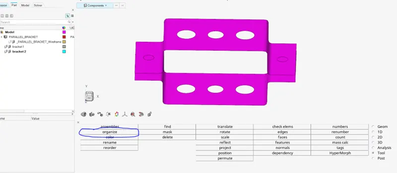
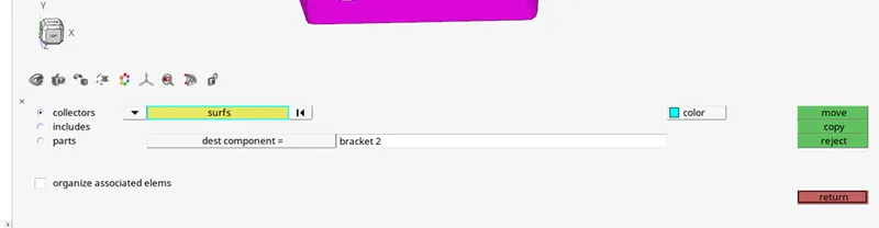
- Select surfs and select the surface on the screen to move the surface to bracket 2 component.
- Before that make sure to select “dest component” as bracket 2, as it indicates your destination component.
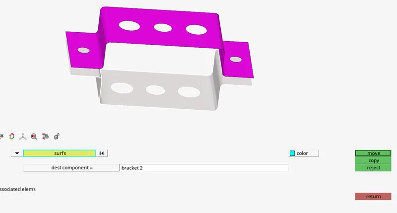
- Click on move and the surface will be moved to bracket 2 components.
- Now let’s do 2D meshing of element size 5 units.
- Before that do washer split at each and every hole.
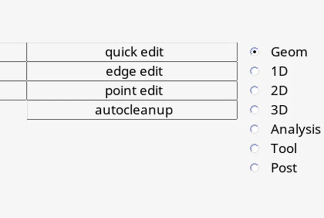
- For that go to any main menu page and select “quick edit”
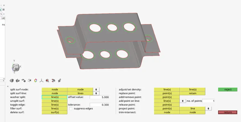
- Select washer split and give offset value as 5.
- Select all the edges of the holes, and the washer split is created.
- Click on return, go to “2D main menu page”, select automesh in it.
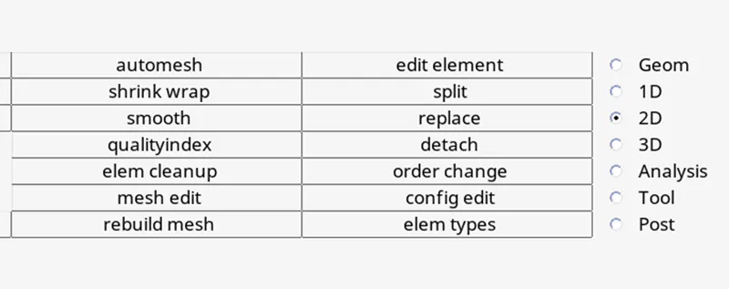

- Set element size as 5 units and mesh type as quads.
- Select all surfaces on screen and click mesh.
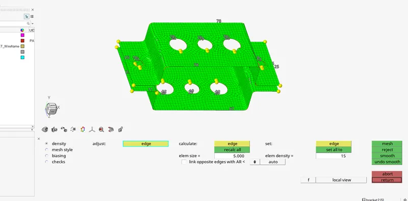
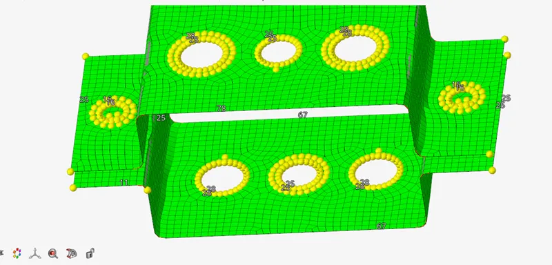
- Increase or decrease number of nodes at washer area and set it to equal to each other. And click mesh again.
- To capture geometry with elements at filleted areas, split the surface with lines at fillets.
(areas shown in images).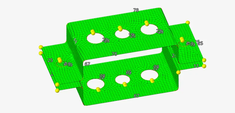
- To do so, go to geom main menu page click on line.
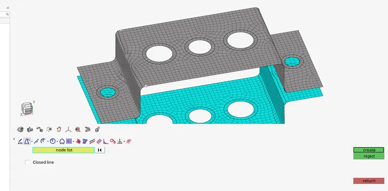
- Select linear nodes, select nodes of elements on screen and click on create.
- Do the same for every filleted area.
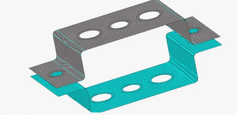
- Split the surface with these lines by using surface edit tool.
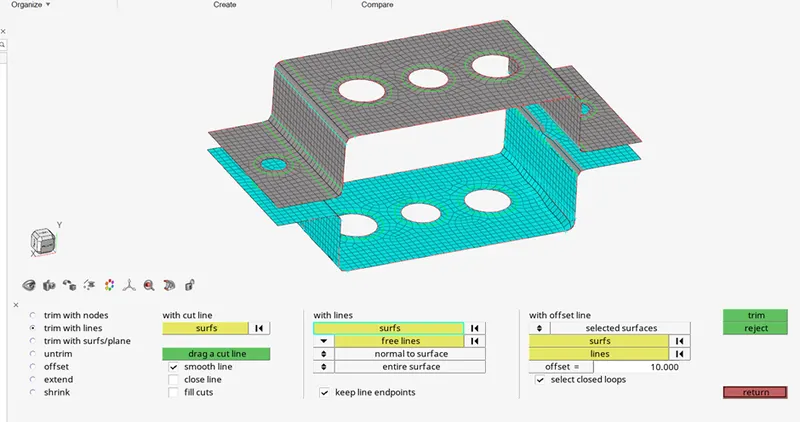
- Select surfs and free lines on screen and click on trim.
- Now again mesh the surfaces and increase number of nodes at fillet area to properly capture the surface with elements.
Ques: 2 creating 1D rod element with RBE2 element and with translational DOF constrained.
Ans: Steps:
- Go to 1D main menu page and select rigids.

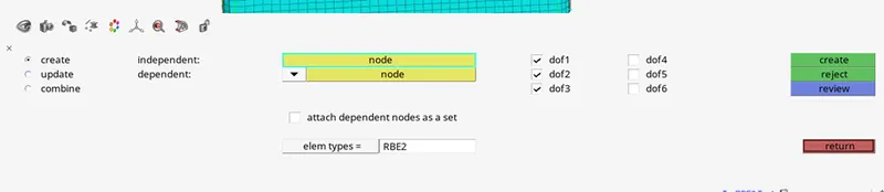
- Deselect Dof4, dof5 and dof6.
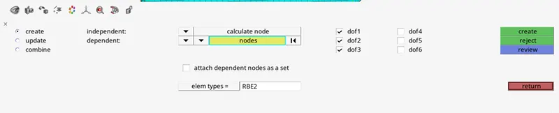
- Change selections for nodes to multiple nodes and nodes to calculate nodes.
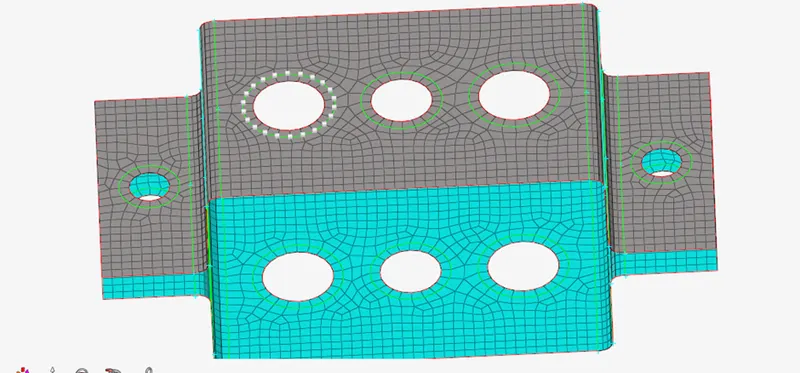
- Select nodes like this and click on create.
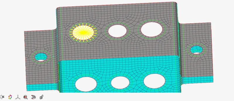
- A cluster of RBE2 elements will be created, also called as RBE2 link.
- Do the same on bracket 2. (grey component name is bracket 1 and cyan coloured component name is bracket 2)
- Select rods in 1d main menu page to create a rod element.
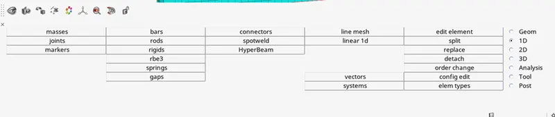

- Select element type as CROD.
- Select nodes as shown in pic, in the centre of pinhole.
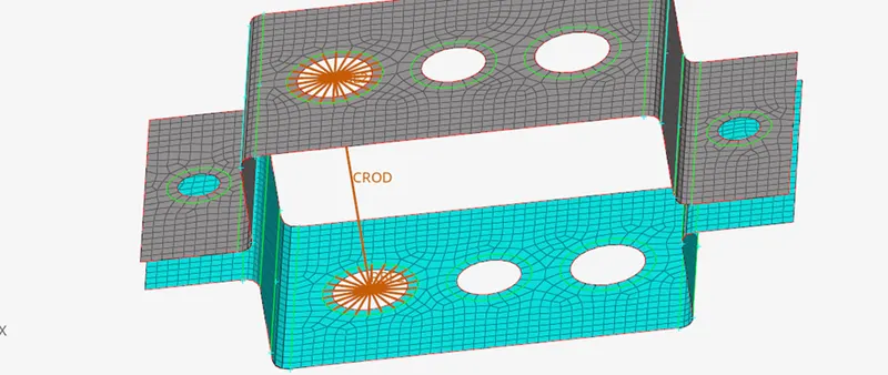
- Create a property by right clicking in tab bar, select property, in that select PROD, as we are defining a rod element right now.
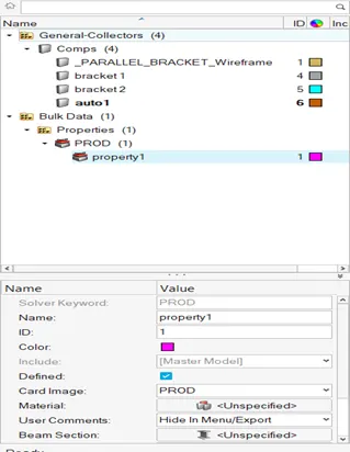
- Rename property1 as Rod.
- Right now we cant assign the rod property to the rod as we didn’t define rod’s section.
- So create a rod section go to hyperbeam in 1D main menu page.
- After selecting hyperbeam, this option will be displayed on screen.
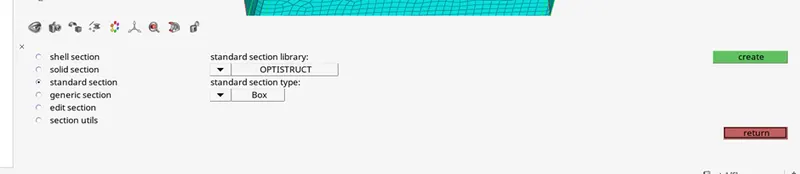
- In this select “standard section”
- in standard section library, select “optistruct”.
- In standard section type, select “box”, then click on create.
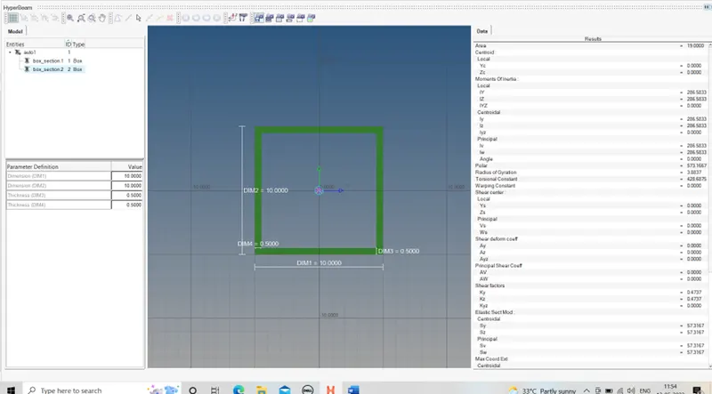
- After clicking on create, this window will open and here, define the cross sectional dimensions in parameter definition.
- Here type DIM1=12, DIM2=10 and Thickness DIM3 and DIM4 as 0.75.
- Now select “rod” in tab bar in property dropdown.
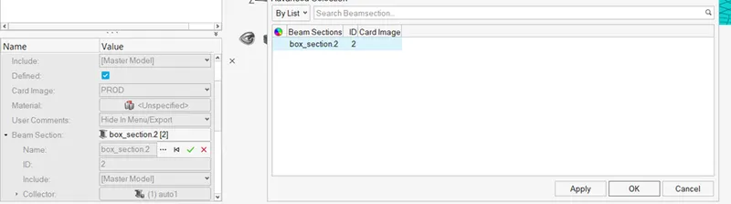
- Now click on beam section.
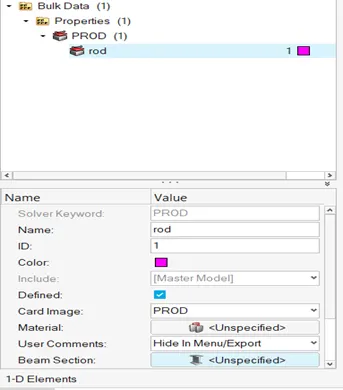
- This dialogue box will open, select the “box_section2” and click on apply and ok.
Ques:3 Beam element
Ans: steps:
Do the same process for beam element and bar element as done in question no. 2.
Just change the link type to RBE3 link and cross section as I section with given parameters.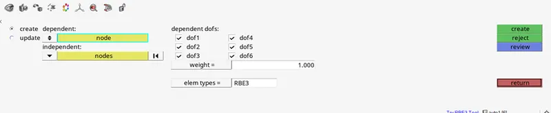
Constraining all DOFs. For RBE3 link.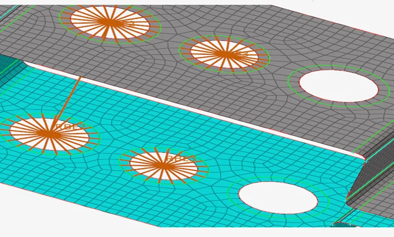
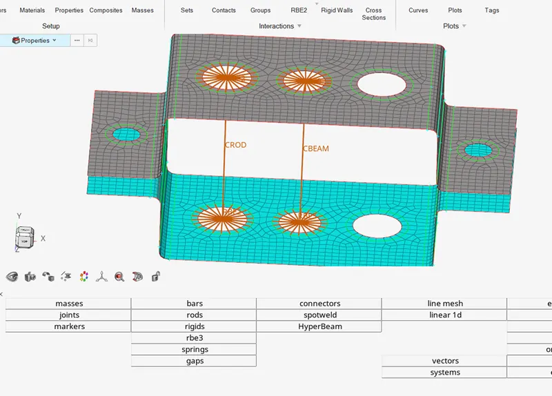
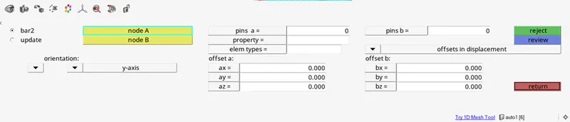
To apply beam element go to bars and select element type as CBEAM.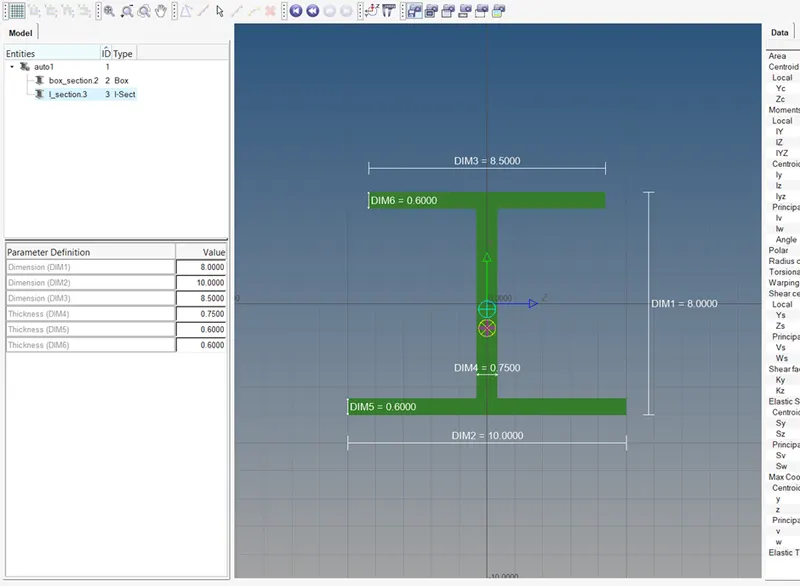
Creating I cross section by using hyperbeam option with specified parameters.
Assign beam property to it also.
Ques 4: Bar element
Ans: steps:
This one also follows same steps as done in question 2 with some changes.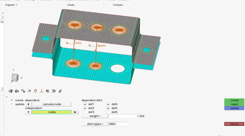
Constrained only x and y DOFs with RBE3 link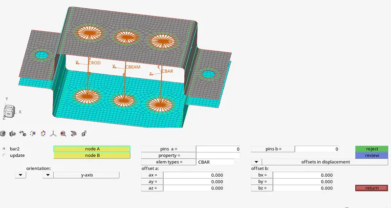
Created a bar element.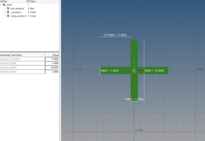
Created a x section also known as “cross” with specified parameters.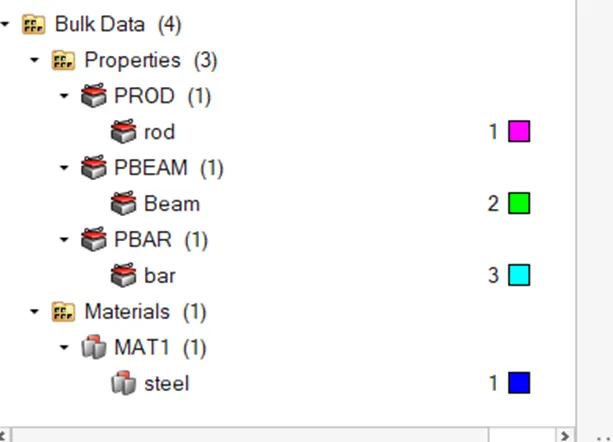
Again create a new property as Pbar and assign cross section X to this property.
Ques:5 apply the mass of magnitude 10 with rbe2 link.
Ans: steps:
- Create Rbe2 link at d and e pin holes (process explained in ques 2).
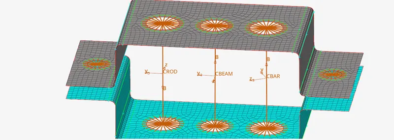
- Left one is d and right one is e pin hole.
- Now to create mass go to 1D main menu page select masses.

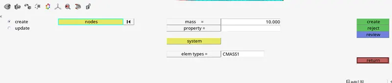
- Assign mass as 10 units.
- Select elem types as CMASS1.
- Select node at the center of rbe2 link at d and e both.
- Then click on create.
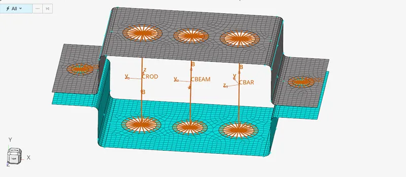
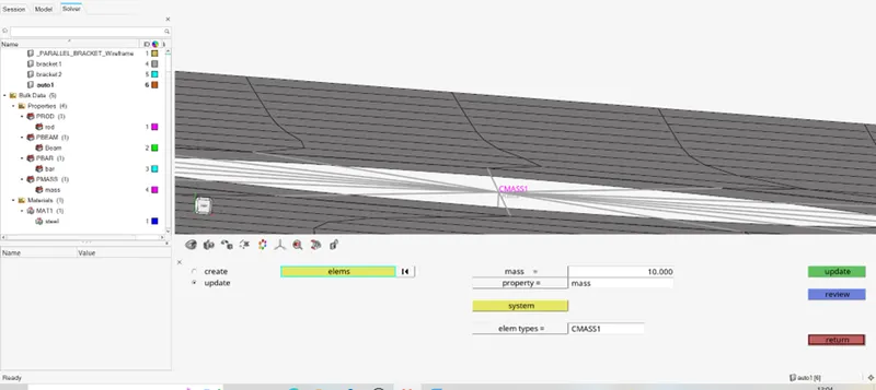
- Create a property as mass and assign mass to the CMASS1 by using update option in masses and assign property as mass.
- Do the same for both pin holes d and e.
Ques:6 Join the two components with spring elements.
Ans: Steps:
- First create a rbe 2 links at both pin hole “f”.
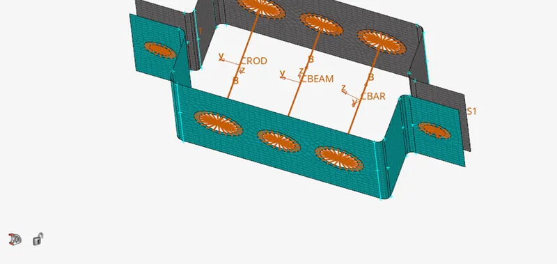
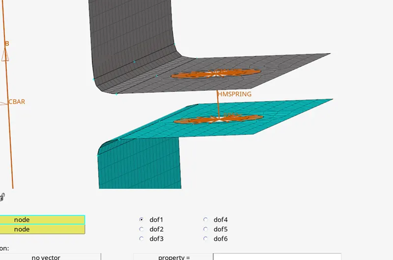
- Now create a spring element connecting “pin hole d” to “pin hole f” and “pin hole e” to “pin hole f”.
- To do so, click on springs in 1D main menu page.
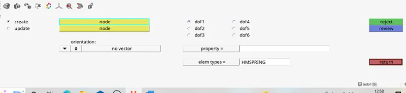
- Here select element type as HMSPRING.
- Select nodes as shown in pic.