Week 9-Creation of 1D Connectors Challenge
Week - 9: Connectors
Objective: To mesh the given 2D surface model and join the components using different connectors as mentioned above in the challenge.
This leads to knowing about the usage of connectors in hypermesh and definitions of connectors.
Getting started from the given model:
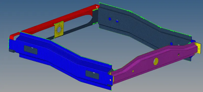
The given model is a frame of vehicle which supports the sprung mass. It has been converted into 2D surface due to uniform thickness, hence as we know that a 2D problem is very accurate and lead time to get the expected solution. The given model maximum should be covered with quad elements with exceptional trias on a few regions for the purpose of capturing the surfaces.
Topology refinement should be done. Symmetrical components can be meshed with mirror option to reduce the time for meshing again.
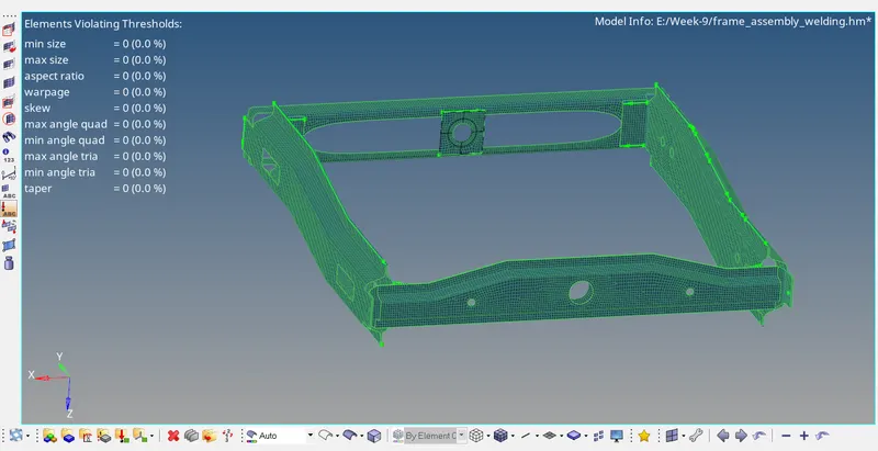
Before using connectors in the meshed model. Qulaity index of the meshed model should be checked.
Assign property card for every components
The below parameters should be used and connections are made
1. Right_Rail_2 & Front_truss_1:- Seam-Quad(angled+capped+L)
2. Left_Rail_2 & Front_truss_1:- Quad elements
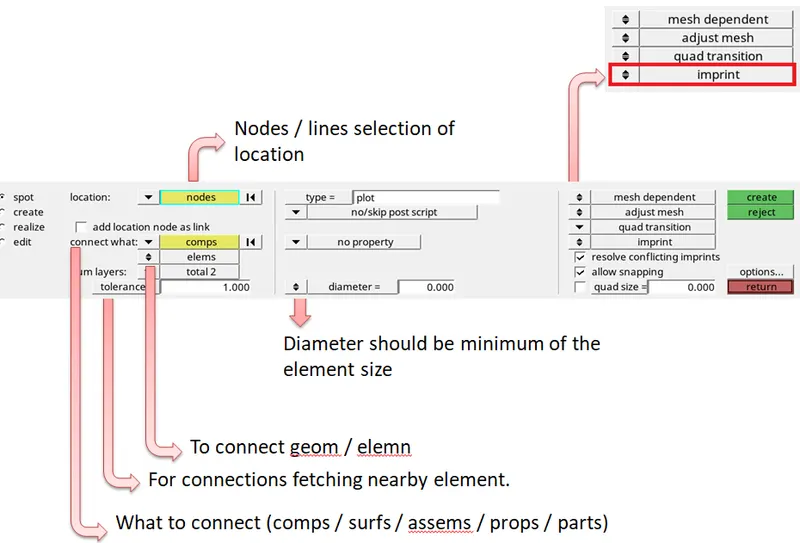
3. Front_truss_2, Front_truss_1 & Right_Rail_1:- Spot weld with 2 Layers and 5 mm Diameter
4. Front_truss_2, Front_truss_1 & Left_Rail_1:- Hexa (Adhesive)
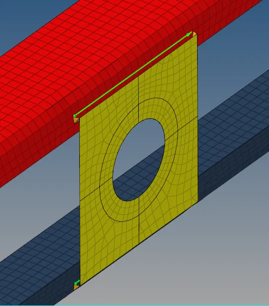
5. Rear_truss_2 & Right_Rail_2:- Bolt Connector
6. Rear_truss_2 & Left_Rail_2:- Bolt Connector
7. Right_Rail_1 & Right_Rail_2:- Spot-weld with Rigid Elements
8. Left_Rail_1 & Left_Rail_2:- Spot-weld with Spring Elements
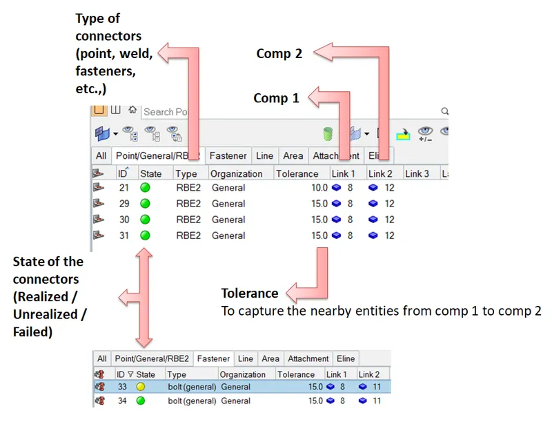
Generally, connectros are geometric entitites which are used to connect the FE entities. (dependent and independent connections). The connectos should be realized, below image shows that one can verify that the given connectors are realized.
"GREEN" color indicates that the connetions are realized. i,e., Elements are connected successfully
1. To create seam-quad (angled+capped+L)

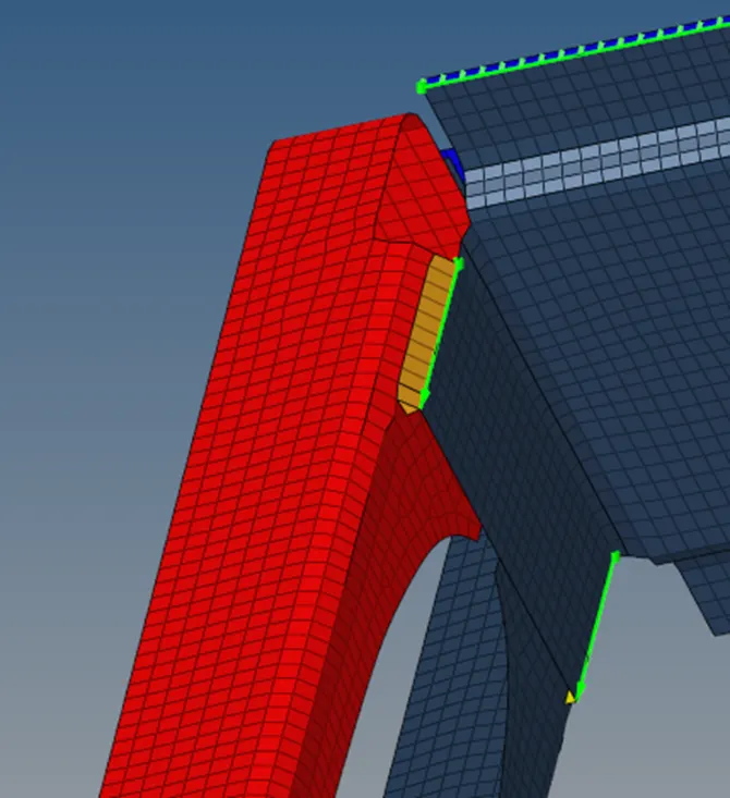
2. Left_Rail_2 & Front_truss_1:- Quad elements
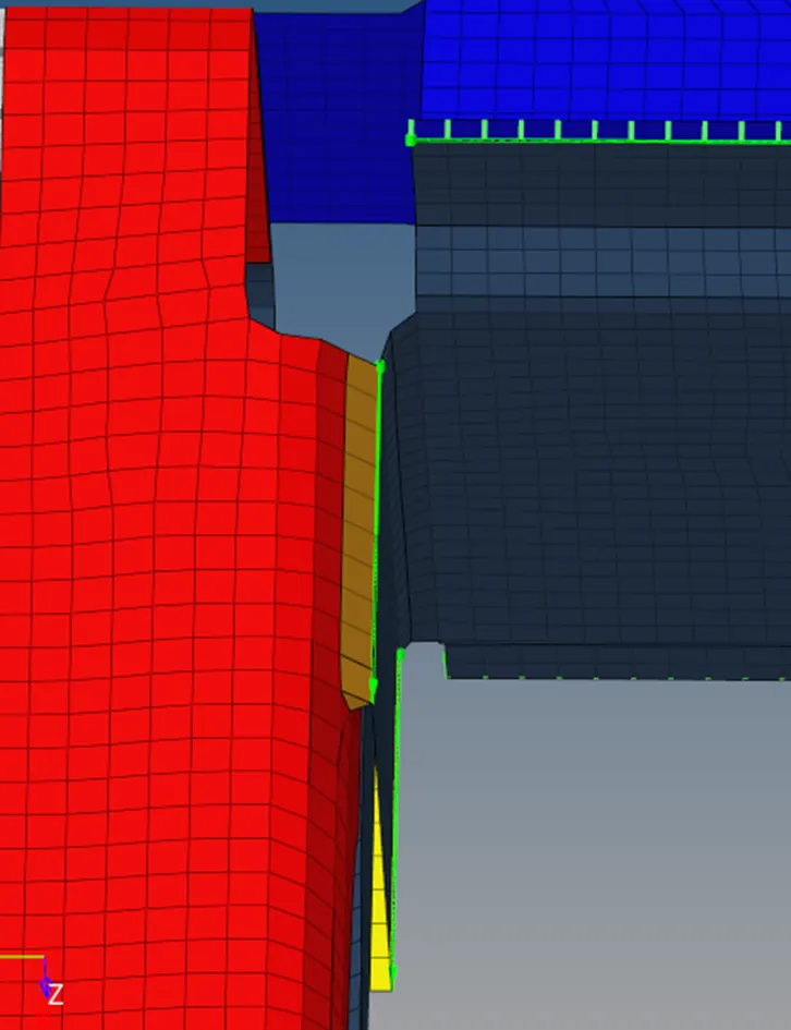
3. Front_truss_2, Front_truss_1 & Right_Rail_1:- Spot weld with 2 Layers and 5 mm Diameter
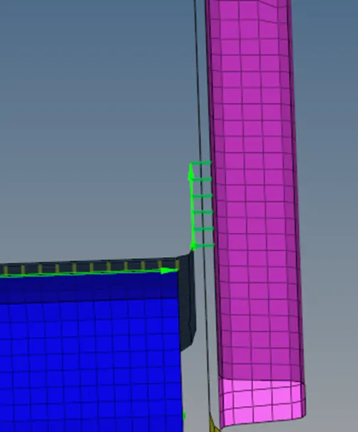
4. Front_truss_2, Front_truss_1 & Left_Rail_1:- Hexa (Adhesive)
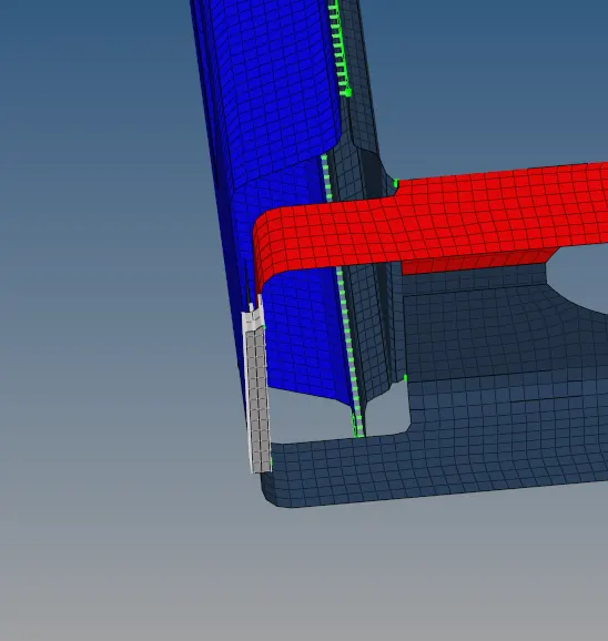
5. Rear_truss_2 & Right_Rail_2:- Bolt Connector
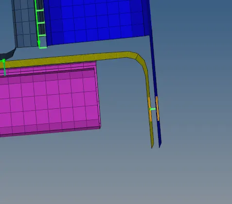
8. Left_Rail_1 & Left_Rail_2:- Spot-weld with Spring Elements
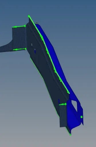
Remaining component successfully connected
Conclusion:
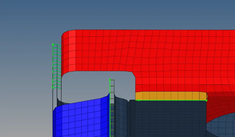
Every components have been meshed and required connectors have be defined and sucessfully realized.
Finally the entire connections and meshed components are shown below