Week 12:Project-1-Meshing of Door Inner Panel Challenge
Week 12:Project-1-Meshing of Door Inner Panel Challenge
Short understanding on the provided Component: Door Inner Panel. (Automotive)
Car Door inner panel, an interior part inside the door, it should possibly withstand the conditions like opening or closing the door, followed by the minimising the vibrations and side collision of the car. The purpose of choosing the PP material where the manufacturing cost is low and it is having higher toughness
Material used: Polypropylene. A Thermoplastic polymer, therefore easily formable through plastic moulding process (Injection process)
Objective: To generate a 2D mesh on given door inner panel. The uniquness in this challenge is that provided model is plastic, i.e., varied thickness.
1. To convert the given 3D model to 2D surface.
- Import the given model. use file ==> open ==> model. From the model, one couldnt able to predict the average thickness of the component, hence this is a plastic component.
- Solid of the given model has to removed. The reason, idea of mesh is to split the surface into finite elements and nodes, then these nodes and elements will distribute the applied load or vibration. These nodes and elements will be having separate stiffness which will be assigned through the material properties like young's modulus (E), Poisson ratio, thickness, Shear modulus, etc.,
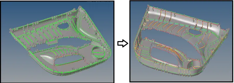
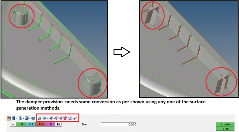
Let's discuss how many ways the conversion on 3D to 2D surface can be done.
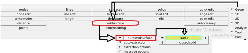
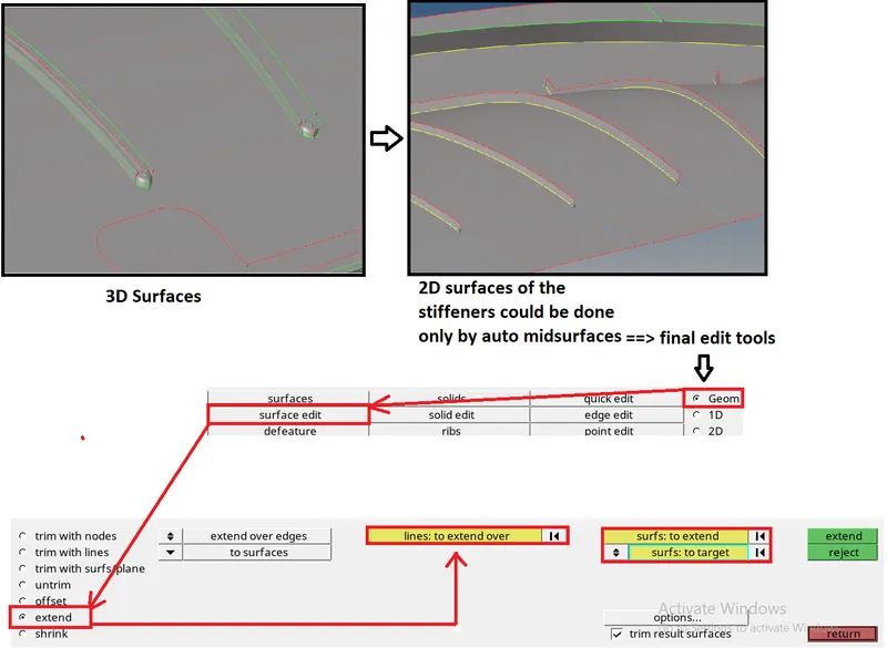
1. Auto-Midsurface. Geom ==> midsurface ==> drop down auto midsurface ==> surfs ==> displayed ==> extract.
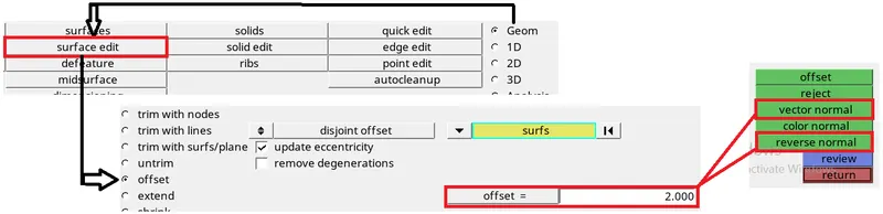
2. Manual offset method. Geom ==> surface edit ==> offset ==> surfs ==> value to be offset ==> vector normal if the generation direction is not in between the two surface then pick reverse normal. ==> return.
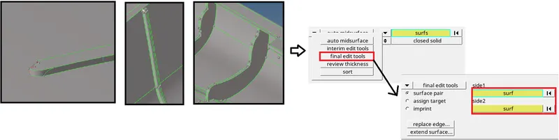
Now, after getting the required surface. we have to clean up the surface. The generated surface, will have some gaps or irregulatiries or improper connectivity like free edges. If the surfaces is connected with only one adjacent surface then green color edges is denoted. if it is coonected with more than one surface then it is denoted by yellow line. Free edges denoted by red line.
2. Topology optimization is must before generating the mesh on created 2D mid surface.
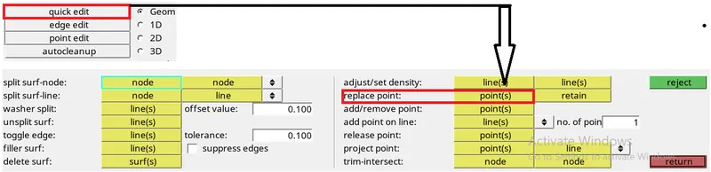
Here are the few commands which helps to optimize the topology
CAUTION: The usage of replace option should be neglibile here, it will connect the surfaces inappropriate. Often usage of replace points leads to discontinuties in the surface recreation which results bad quality mesh.
3. To generate mesh without comprmising the quality:
The given quality crieteria
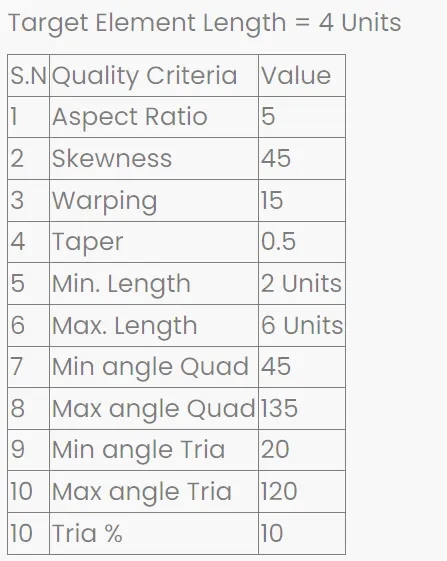
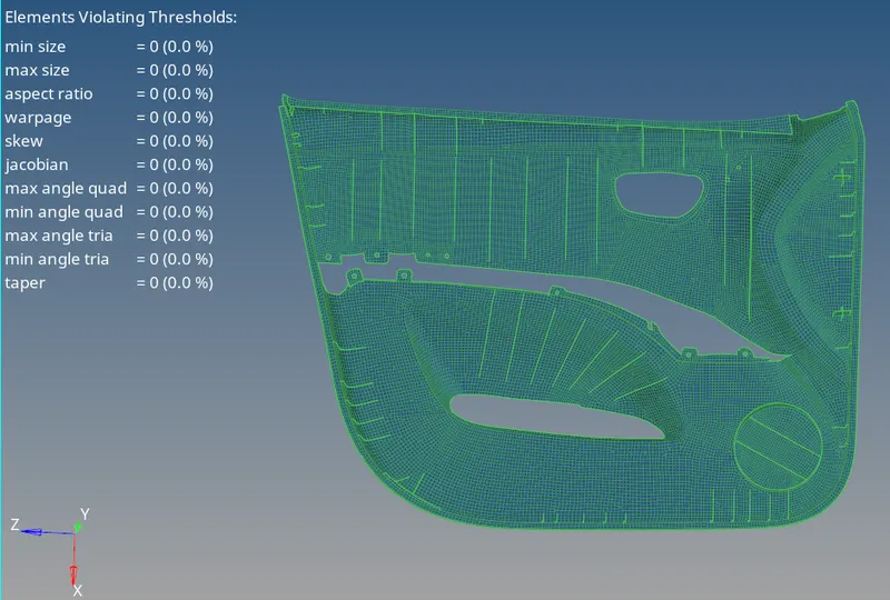
min & max size: To check for the minimum and maximum feature length captured and the presence of any non zero length element.
Hypermesh finds the minimal nearby length of the element. (minimal normalised height [MHN])
Min element length = min (hi) / 2 x sqrt (3)
The closest distance to the rays containing the legs of the quadrilateral that do not include the node.
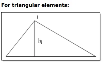
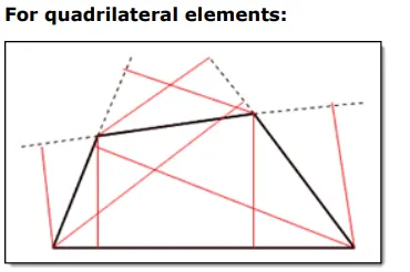
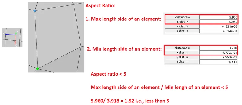
aspect ratio: It is calculated by dividing the maximum length side of an element by the minimum length side of the element. If aspect ratio of the quad exceeds the provided ratio then nodes to be moved nearer to make (using Tools ==> Translate)
warpage: Warpage is not applicable for trias. The quads are splitted into two trias and finding the angle between the two planes which trias form. The quads diagonals are splitted form a normal plane, then angel between the normal planes is called as warping angle.
Maximum warp angle: 15 degree
Skew:
Skew for Traingle:
It is calculated in trias. Angle between one corner of the triangle (node) to the bisecting the opposite side of the line and vector
To find the minimum angle between the vector from each node to opposing mid-side and the vector between the two adjacent mid-sides at each node of the element.
Skew for Quad:
Minimum angle between two lines joining opposite mid-sides of the element.
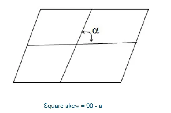
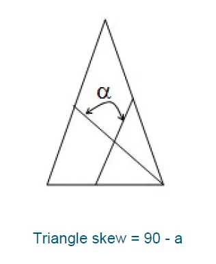
Taper:
Spitting the quadrilateral into different trias and finding the area of them. Subtracting the ratio of A(tria) and half of the Area of total quadrilateral
A(tra) = Area of a + Area of b + Area of c + Area of d
taper = 1 - [A(tria) / 0.5 * A(quad)]
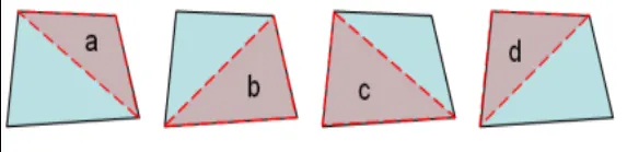
Jacobian: Jacobian matrix or gauss point which tells deviation in the shape of the element. Each elemet has its own perfect form. This jacobian matrix tells the deviation from the perfect of element while capturing the surfaces. It should be within the 0.0 to 1.0.
Creation of autothickness:
To create auto thickness, for the created surfaces from Mesh ==> Assign ==> Mid mesh thickness
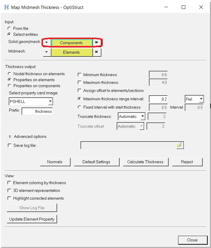
Update the thickness with material. Create a material card in this case, used polypropylene.
Conculsion:
The above project has been meshed within the quality criteria and created auto thickness for the plastic component. The material card has been created and assigned for the mapped thickness.