Week 9-Creation of 1D Connectors Challenge
Aim:
To create Create 1D connector and Attach the various meshed parts of the given model
Procedure:
- Right_Rail_2 & Front_truss_1:- Seam-Quad(angled+capped+L)
Procedure:
Select the above mentioned Meshed components
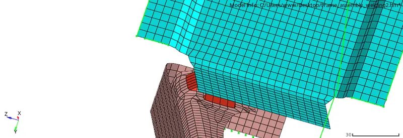
Settings:
1)1D>Connectors>seam
2)Location:Node by path
3)Spacing:5
4)Connector type: Seam-Quad(angled+capped+L)
5)Comp:choose the mentioned components as above
5)Tolerance:10
6)Then Press create button
7)Do correction for failed node selection until to get full realization which is shown in green color connector
- Left_Rail_2 & Front_truss_1:- Quad elements
Procedure:
Select the above mentioned Meshed components
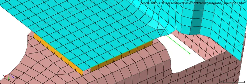
settings
1)1D>Connectors>seam
2)Location:Node by path
3)Spacing:5
4)Connector type: Seam-Quad
5)Comp:choose the mentioned components as above
5)Tolerance:10
6)Then Press create button
7)Do correction for failed node selection until to get full realization which is shown in green color connector
3)Front_truss_2, Front_truss_1 & Right_Rail_1:- Spot weld with 2 Layers and 5 mm Diameter
Procedure:
Select the above mentioned Meshed components
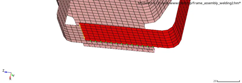
settings
1)1D>Connectors>spot
2)Location:Node by path
3)Spacing:5
4)Connector type: spot weld with dia 5mm
5)Comp:choose the mentioned components as above
5)Tolerance:10
6)Then Press create button
7)Do correction for failed node selection until to get full realization which is shown in green color connector
- Front_truss_2, Front_truss_1 & Left_Rail_1:- Hexa (Adhesive)
Procedure:
First Select the above mentioned Meshed components
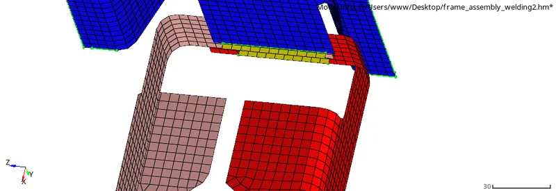
settings
1)1D>Connectors>seam
2)Location:Nodes
3)Spacing:5
4)Connector type: Hexa Adhesive
5)Comp:choose the mentioned components as above
6)Total no of components:3
7)Tolerance:10
8)Then Press create button
5)Rear_truss_2 & Right_Rail_2:- Bolt Connector
Procedure:
First Select the above mentioned Meshed components
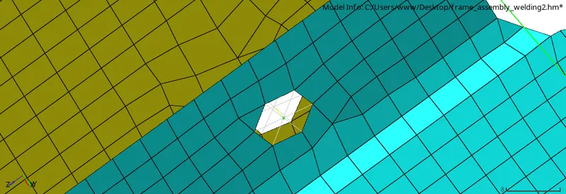
settings
1)1D>Connectors>Bolt
2)Location:Nodes
3)Spacing:5
4)Connector type: CBAR
5)Comp:choose the mentioned components as above
6)Total no of components:2
7)Tolerance:10
8)select Create with holes when no holes
9)Then Press create button
- Rear_truss_2 & Left_Rail_2:- Bolt Connector
Procedure:
First Select the above mentioned Meshed components
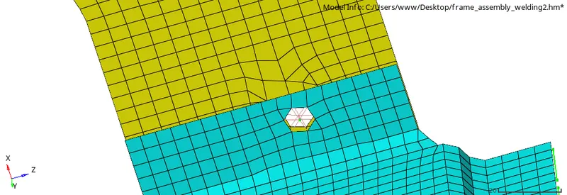
settings
1)1D>Connectors>BOLT
2)Location:Nodes
3)Spacing:5
4)Connector type: bolt spider
5)Comp:choose the mentioned components as above
6)Total no of components:2
7)Tolerance:10
8)select Create with holes when no holes
9)press create button
7). Right_Rail_1 & Right_Rail_2:- Spot-weld with Rigid Elements
Procedure:
First Select the above mentioned Meshed components
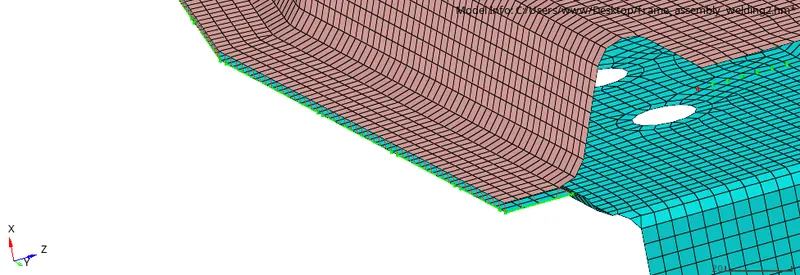
settings
1)1D>Connectors>spot
2)Location:Node by path
3)Spacing:5
4)Connector type: Rigid
5)Comp:choose the mentioned components as above
6)Total no of components:2
7)Tolerance:10
8)Then Press create button
9)Do correction for failed node selection until to get full realization which is shown in green color connector
- Left_Rail_1 & Left_Rail_2:- Spot-weld withSpring Elements
Procedure:
First Select the above mentioned Meshed components
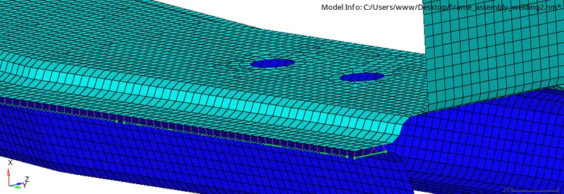
settings
1)1D>Connectors>spot
2)Location:Node by path
3)Spacing:5
4)Connector type: Spring
5)Comp:choose the mentioned components as above
6)Total no of components:2
7)Tolerance:10
8)Then Press create button
9)Do correction for failed node selection until to get full realization which is shown in green color connector
9) Front_truss_2, Front_truss_1 & Reinf plate:Area(Adhesive)
Procedure:
First select the meshed components as above
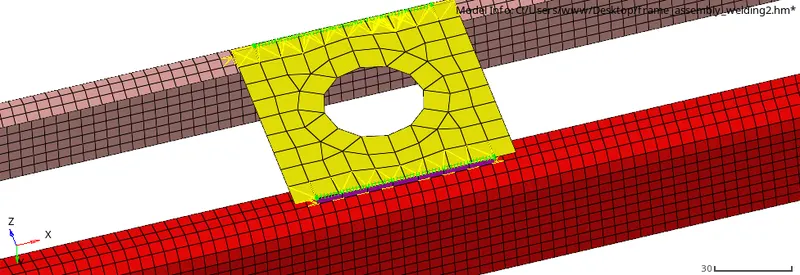
Settings
1)1D>Connectors>Area
2)Location:Node by path
3)Width and offset default value
4)Connector type: Adhesive
5)Comp:choose the mentioned components as above
6)Tolerance:10
7)Then Press create button
9)Do correction for failed node selection until to get full realization which is shown in green color connector
10)All components assembly Connected with 1D Connectors
Procedure
Select the all meshed components
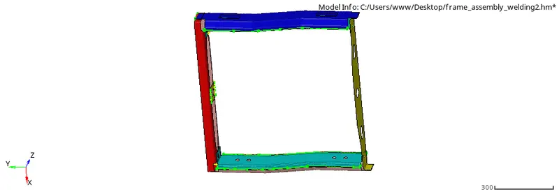
Files attachéd:
1)Frame_assembly_welding2.hm