Week 9-Creation of 1D Connectors Challenge
Week9 – Challenge
Frame Assembly Welding
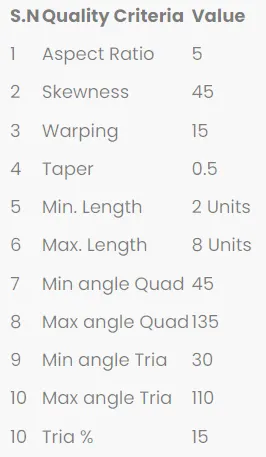
Objective: To mesh the given geometry. Model mesh should pass below quality requirements.
Target Element size= 5 units
CAD model image:
Open the HM file. The imported geoemetry looks as below
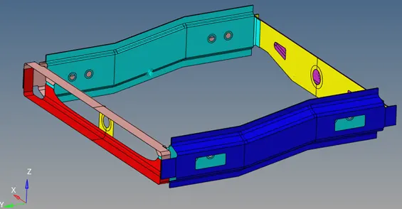
Figure: CAD model
Procedure with required images:
Step-1:
The model geometry is checked for any issues. Toggle by 2D Topo
Step-2:
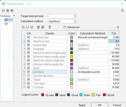
Preferences-> Criteria file settings->set the below criteria for 2D
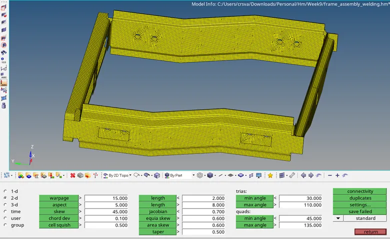
Step-3: 2D->automesh->surfaces(displayed)->mesh type=mixed->element size=5mm->mesh
Step-4:
F10-> 2D-> check quality. Save failed and F5->retrieve->mask
Find attached. Remesh. Then check quality again same as above.
2D->quality index-> cleanup tools
2D->elem cleanup
Step-5:
- Right_Rail_2 & Front_truss_1: Seam-Quad(Angled +capped+L)
1D->connectors->type (Seam)->Seam-Quad(Angled+capped+L)
Below options were selected to create the seam weld connector.
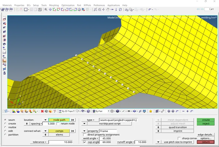
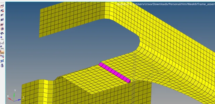
Figure: Right_Rail_2 & Front_truss_1: Seam-Quad(Angled +capped+L) Final model
- Left_Rail_2 & Front_truss_1: Quad elements
1D->connectors->type (Seam)->Seam-Quad
Below options were selected to create the seam weld connector.
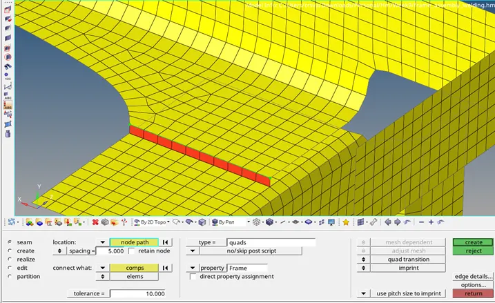
Figure: Left_Rail_2 & Front_truss_1: Quad elements Final model
- Front_truss_2, Front_truss_1 & Right_Rail_1: Spot weld with 2 Layers and 5mm Diameter
1D->Connectors->spot weld
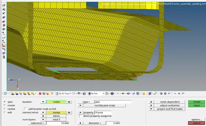
Figure: Front_truss_2, Front_truss_1 & Right_Rail_1: Spot weld with 2 Layers and 5mm Diameter Final model
- Front_truss_2, Front_truss_1 & Left_Rail_1: Hexa (Adhesive)
1D->Connectors->Hexa (Adhesive)
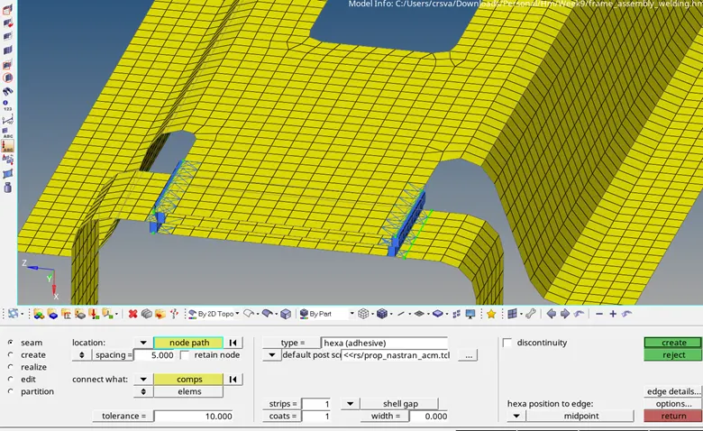
Figure: Front_truss_2, Front_truss_1 & Left_Rail_1: Hexa (Adhesive) Final Model
- Rear_truss_2 & Right_Rail_2: Bolt Connector
1D->Connectors->Bolt(general)
As the local mesh of the components got distorted, mesh was optimized by using f10->save failed->2D-> elem cleanup
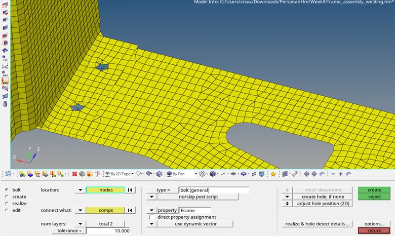
Figure: Rear_truss_2 & Right_Rail_2: Bolt Connector Final Model
- Rear_truss_2 & Left_Rail_2: Bolt Connector
1D->Connector->Bolt-> Bolt(CBAR)
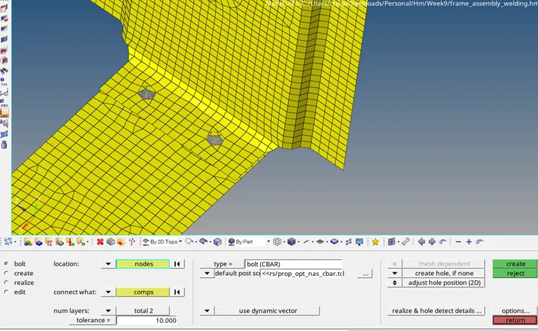
Figure: Rear_truss_2 & Left_Rail_2: Bolt Connector Final Model
- Right_Rail_1 & Right_Rail_2: Spot-weld with Rigid Elements
1D->Connectors->spot (Type= Rigid). This creates RBE2 links
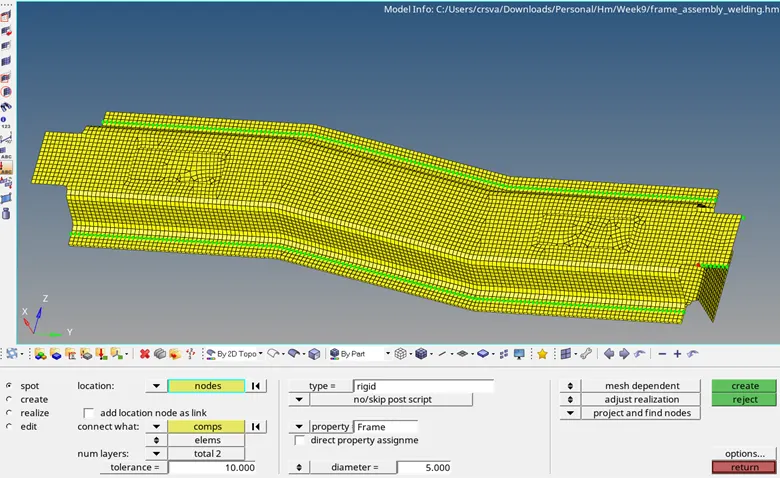
Figure: Right_Rail_1 & Right_Rail_2: Spot-weld with Rigid Elements Final Model
- Left_Rail_1 & Left_Rail_2: Spot-weld with Spring Elements
1D->connectors->Spot->Type=spring. This creates CELAS (elastic) elements.
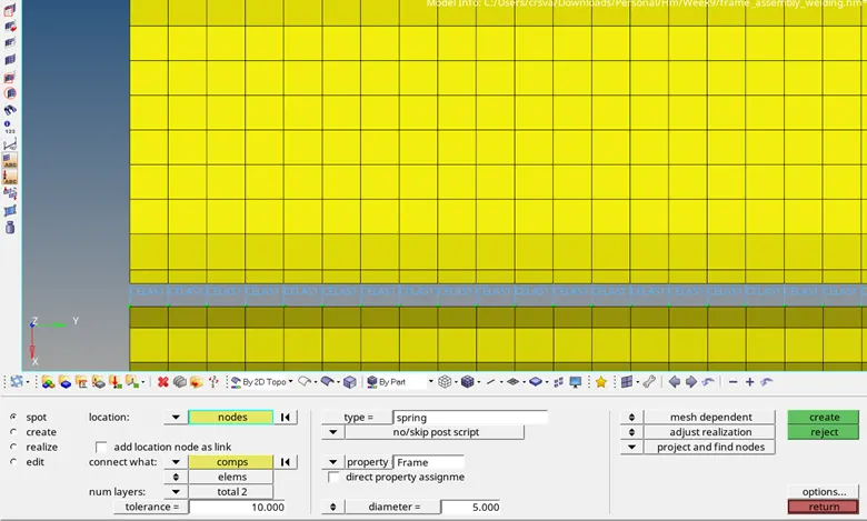
Figure: Left_Rail_1 & Left_Rail_2: Spot-weld with Spring Elements Final Model
- Rest all the components left join them with suitable connectors
Between Left_Rail_1 and Rear_Truss_2, Bolt connector was used.
1D->Connectors->Bolt(Type=Spider)
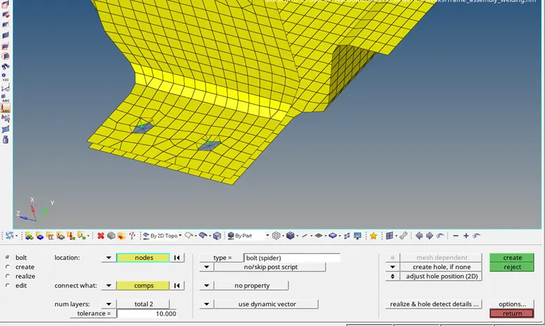
Between Right_Rail_1 and Rear_Truss_2 Hexa (adhesive) joint was created. With 3 strips and 2 coats as can be seen in below pic.
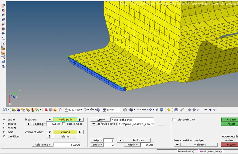
Next is the connection between Rear_Truss_1 and Rear_Truss_2.
On Side of the components was connected using spot weld load transfer type.
1D->connectors->Spot->type=weld
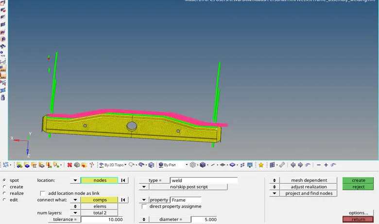
On Other side, seam weld was created
1D->Connectors->Seam->Type=weld
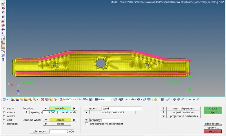
For the reinforcement plate between the Front_Trusss_1 and Front_Truss_2, connection was made using Seam-quads (angles+capped+L) weld option.
1D->connectors-> Seam->type=Seam-quads(angled+capped+L)
On one side, weld angle =60, cap angle =45, runoff angle = 10
On other side, weld angle = 45, cap angle = 75, runoff angle = 10
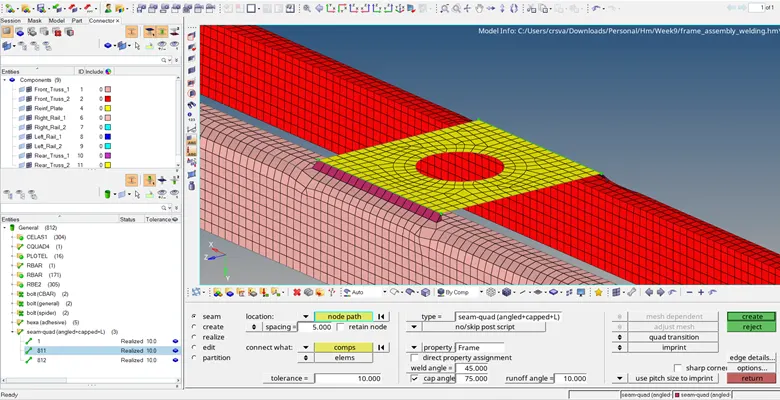
View-> Browser->Hypermesh->Connectors
Entities-> Seam-quads(angled+capped+L)->811->Reverse direction toggles
Right click 811->Realize
Final connectors of the model are as seen below. All components of the model are joined successfully.
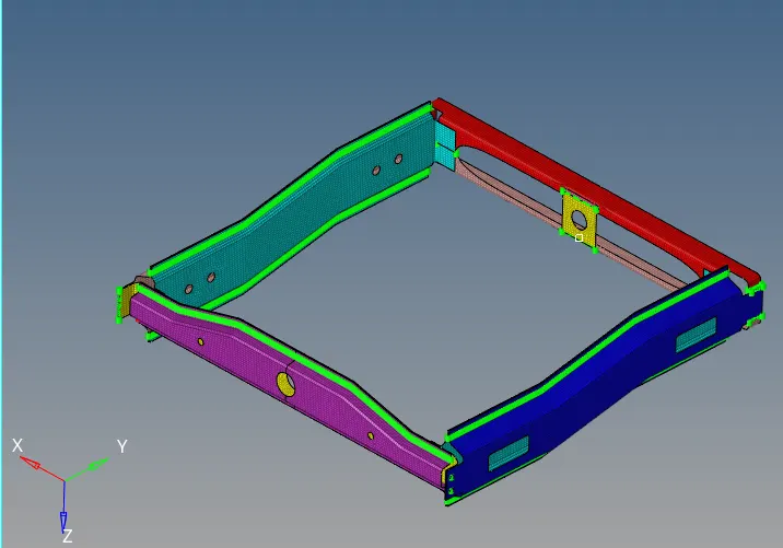
Figure: Final Model