Week 9-Creation of 1D Connectors Challenge
Creation of 1D Connectors
OBJECTIVES:-
To mesh the given geometry and provided below are the quality parameters to follow.
Target Element size - 5 Units
|
S.N |
Quality Criteria |
Value |
|
1 |
Aspect Ratio |
5 |
|
2 |
Skewness |
45 |
|
3 |
Warping |
15 |
|
4 |
Taper |
0.5 |
|
5 |
Min. Length |
2 Units |
|
6 |
Max. Length |
8 Units |
|
7 |
Min angle Quad |
45 |
|
8 |
Max angle Quad |
135 |
|
9 |
Min angle Tria |
30 |
|
10 |
Max angle Tria |
110 |
|
10 |
Tria % |
15 |
Create connectors and Attach the various parts of the given model as per specified below.
1. Right_Rail_2 & Front_truss_1:- Seam-Quad(angled+capped+L)
2. Left_Rail_2 & Front_truss_1:- Quad elements
3. Front_truss_2, Front_truss_1 & Right_Rail_1:- Spot weld with 2 Layers and 5 mm Diameter
4. Front_truss_2, Front_truss_1 & Left_Rail_1:- Hexa (Adhesive)
5. Rear_truss_2 & Right_Rail_2:- Bolt Connector
6. Rear_truss_2 & Left_Rail_2:- Bolt Connector
7. Right_Rail_1 & Right_Rail_2:- Spot-weld with Rigid Elements
8. Left_Rail_1 & Left_Rail_2:- Spot-weld with Spring Elements
9. Rest all the component left Join them with suitable connectors
PROCEDURE:-
Model Introduction:-
The given model is a frame assembly model that contains total of 9 components kept in seperate collectors individually as shown in images below for the convenience.
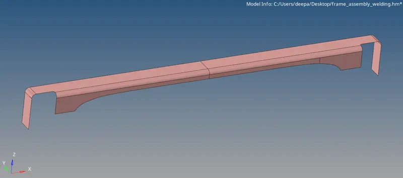
Fig: Front Truss 1
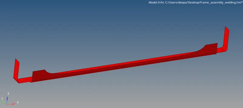
Fig: Front Truss 2
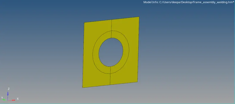
Fig: Reinforcement Plate
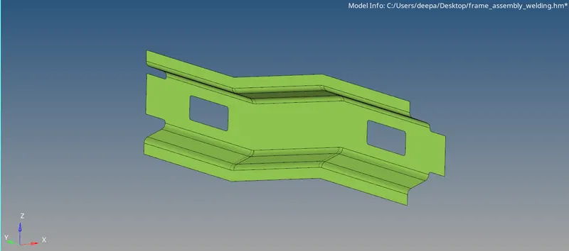
Fig: Right Rail 1
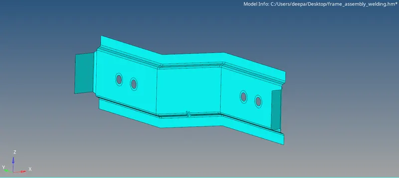
Fig: Right Rail 2
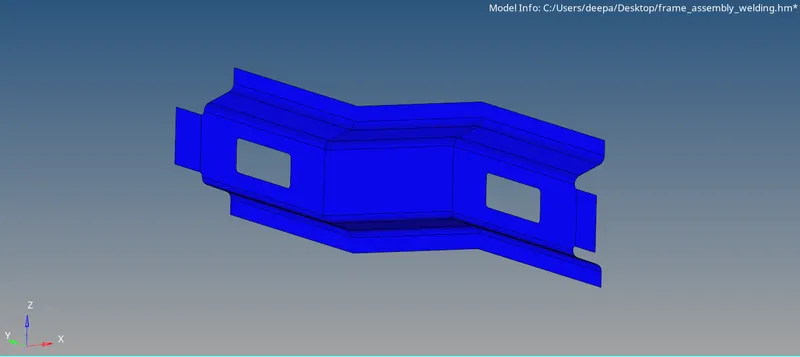
Fig: Left Rail 1
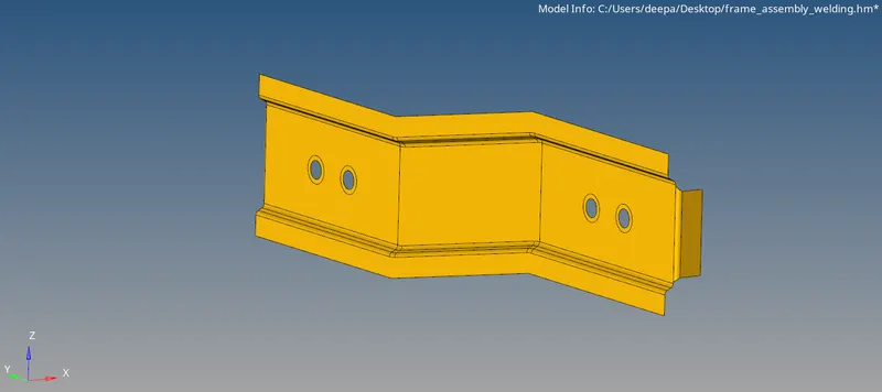
Fig: Left Rail 2
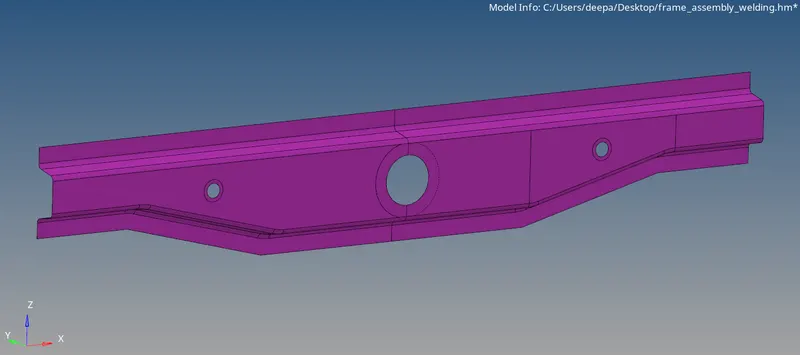
Fig: Rear Truss 1
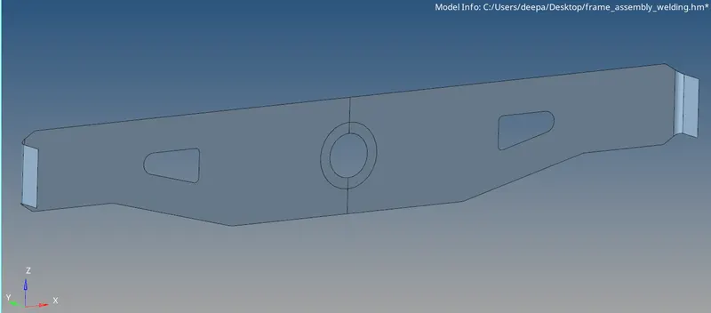
Fig: Rear Truss 2
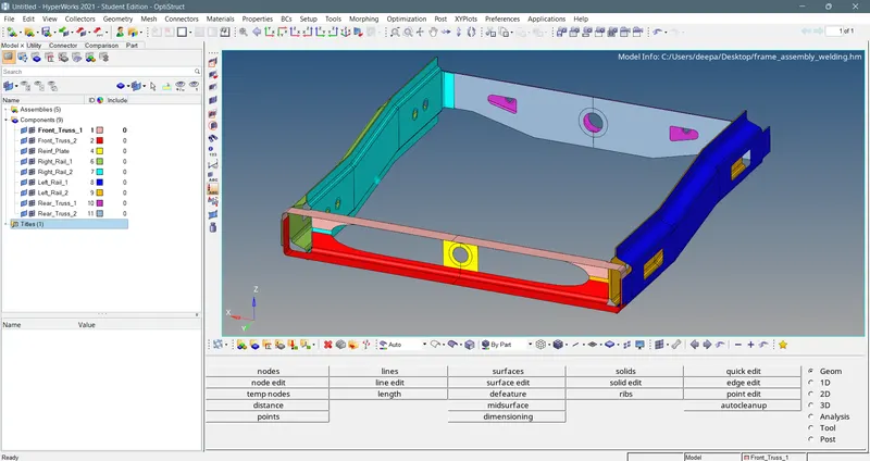
Fig: Model Import
Meshing:-
The model is cleaned up using autocleanup option and by manual efforts. Meshed with proper mesh flow. The mesh type is mixed and element size is taken as 5 mm. It is a 2D mesh since the entire model comprises of extracted midsurfaces already.
Meshed model and quality criteria under which it is meshed, shown in images below.
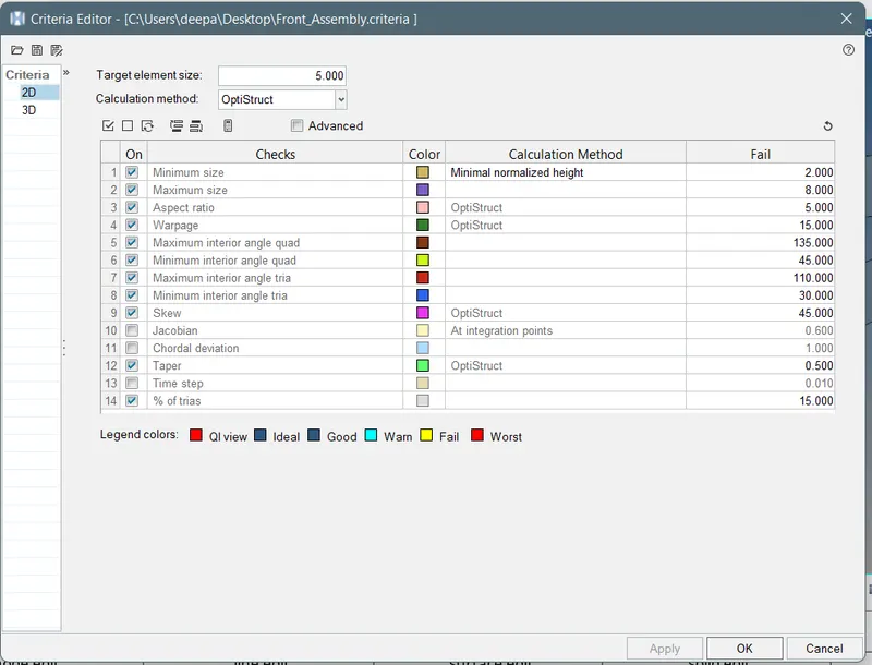
Fig: Quality Criteria
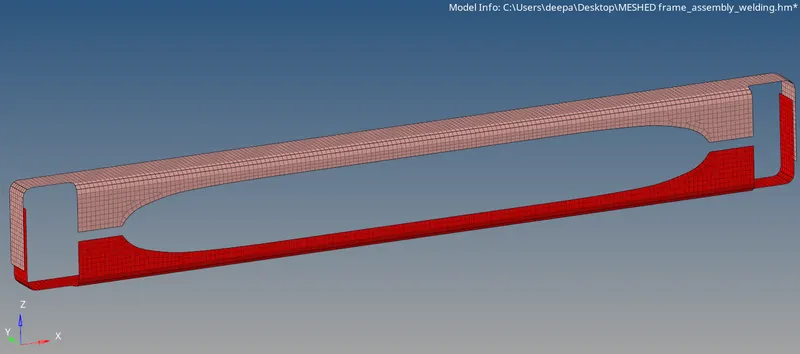
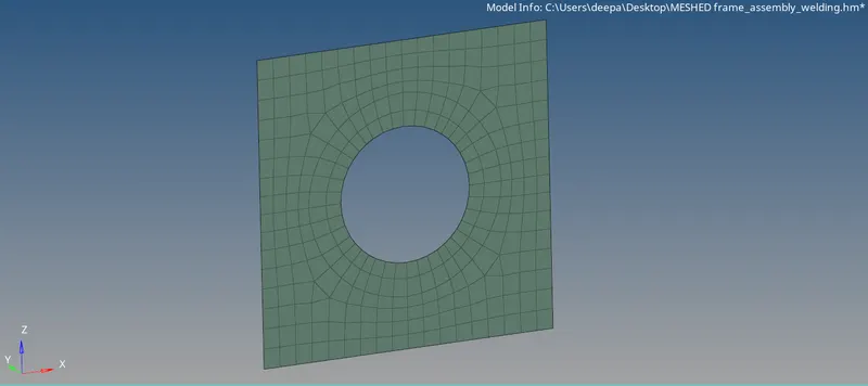
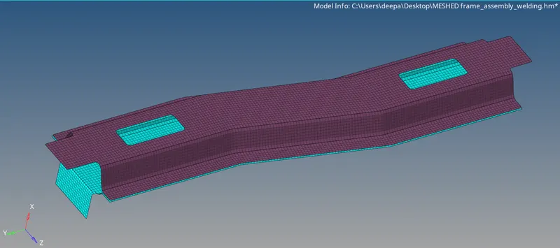
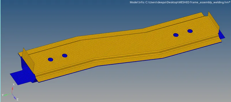
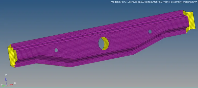
Fig: Individually Meshed Components
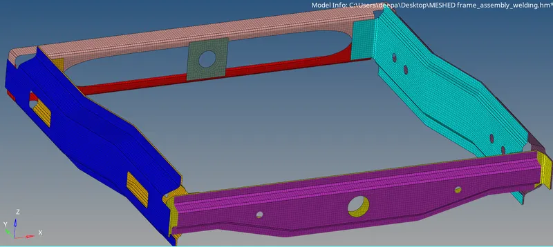
Fig: Meshed Model
Connection Deployment:-
Connectors are geometric entities, which are primarily used to represent the CAD geometric connection in terms of FEA. Connections can be created as a spot-weld, seam-weld, adhesive, bolts and masses. A realized connector will be considered as the successful representation of a CAD model in preprocessing and the connecting parts can be considered as connected.
1) Right_Rail_2 & Front_truss_1:- Seam-Quad(angled+capped+L)
The first connection that needs to be made is between Right_Rail_2 and Front_Truss_1 which is a Seam-Quad(angled+capped+L) connection.
- Select 1D/2D > Connectors > Seam option.
- Now select the location, where the Weld has to be created, by clicking the “node path”.
- Tick the checkbox of “retain nodes” option, to retain the position of the nodes, while creating and realizing a connector.
- Specify the “spacing” value and select the “comps” option under “connect what”, in order to create the weld between those two components.
- Specify the “tolerance” value, based on the distance between the two components.
- Select the type as “seam-quad (angled+capped+L)”.
- Click on the “create” button, to create the seam weld.

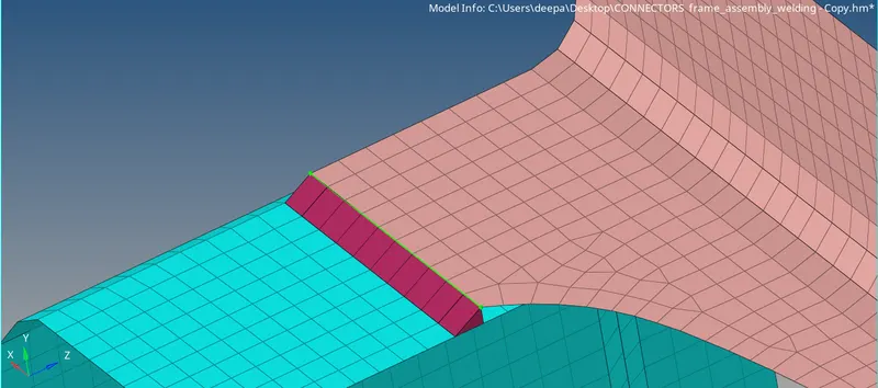
Fig: Seam-Quad(angled+capped+L) Connection
There are some paremeters that a capped seam weld connection contains, so those need to be taken care of -
Spacing:- It is generally kept equal to the target element length of the meshing.
Tolerence:- It is the search radius around a node that the software looks for any component to connect with and generally it is kept either equal to or greater than the distance between the two components that need to be connected with each other.
Weld Angle:- Angle between the normal projection of the nodes and slant length of the weld element. It is recommended to define weld angles between 0 and 90 degree.
Cap Angle:- Angle between the normal of the first slant weld element and its adjacent side element. To define seam weld for 0 to 45 degree cap angle, it is recommended to select ≤10 degree and for the 45 - 90 degree cap angle, it is recommended to select ≥75 degree.
Runoff Angle:- Angle between the normal of the first slant weld element and its adjacent weld elements.It is recommended to define weld angles between 0 and 10 degree.
2) Left_Rail_2 & Front_truss_1:- Quad elements
- Select 1D/2D > Connectors > Seam option.
- Now select the location, where the Weld has to be created, by clicking the “node path”.
- Tick the checkbox of “retain nodes” option, to retain the position of the nodes, while creating and realizing a connector.
- Specify the “spacing” value and select the “comps” option under “connect what”, in order to create the weld between those two components.
- Specify the “tolerance” value, based on the distance between the two components.
- Select the type as “quads”.
- Click on the “create” button, to create the seam weld.

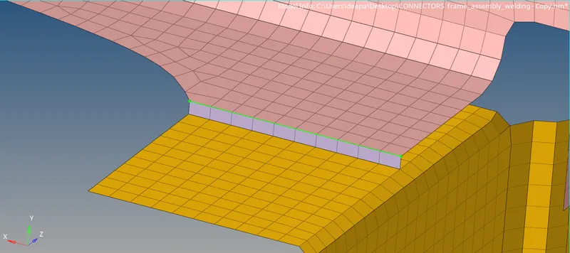
Fig: Quad Elements Connection
3) Front_truss_2, Front_truss_1 & Right_Rail_1:- Spot weld with 2 Layers and 5 mm Diameter
- Select 1D/2D > Connectors > Spot option.
- Now select the location, where the Weld has to be created, by clicking the “node list”.
- Tick the checkbox of “retain nodes” option, to retain the position of the nodes, while creating and realizing a connector.
- Specify the “spacing” value and select the “comps” option under “connect what”, in order to create the weld between those two components.
- Select the number of layers(Number of Components) to be welded, under “num layers” option.
- Specify the “tolerance” value, based on the distance between the two components.
- Select the type as “weld”.
- Click on the “create” button, to create the spot weld.

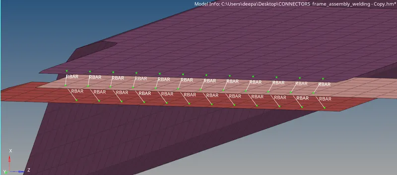
Fig: Spot Weld Connection
4) Front_truss_2, Front_truss_1 & Left_Rail_1:- Hexa (Adhesive)
- Select 1D/2D > Connectors > Seam option.
- Now select the location, where the Weld has to be created, by clicking the “node path”.
- Tick the checkbox of “retain nodes” option, to retain the position of the nodes, while creating and realizing a connector.
- Specify the “spacing” value and select the “comps” option under “connect what”, in order to create the weld between those two components.
- Specify the “tolerance” value, based on the distance between the two components.
- Select the type as “hexa (adhesive)”.
- Click on the “create” button, to create the seam weld.

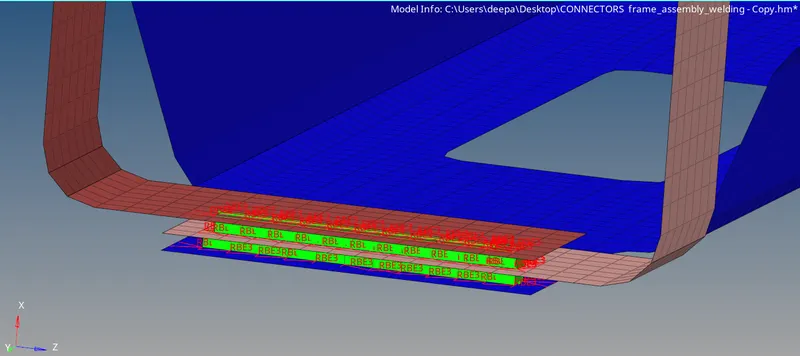
Fig: Hexa(Adhesive) Connection
5) Rear_truss_2 & Right_Rail_2:- Bolt Connector and 6) Rear_truss_2 & Left_Rail_2:- Bolt Connector
In order to create a Bolt connection, if hole is not present in the components, we have to locate a centre node so that hole can be created at that place as shown below.
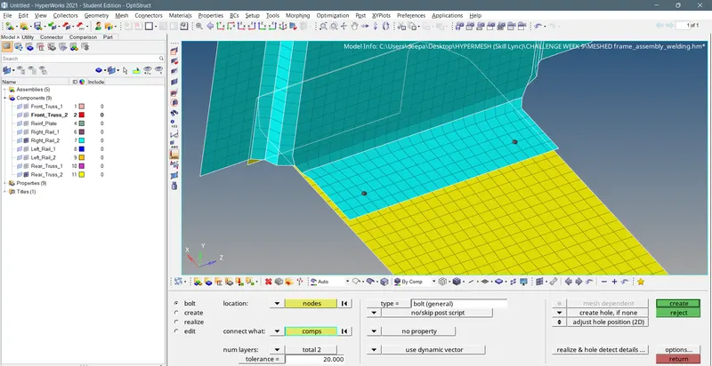
- Now click on the 1D/2D > Connectors > Bolt option.
- Under “location”, select the node, which we created already to establish the bolt connection.
- Then select the “comps” option under “connect what”, in order to create the weld between those two components.
- Select the number of layers to be welded, under “num layers” option.
- Specify the “tolerance” value, based on the distance between the two components.
- Select the type as “bolt (general)”.
- Click on the “create” button, to create the Bolt Connection.

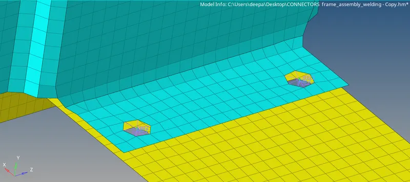
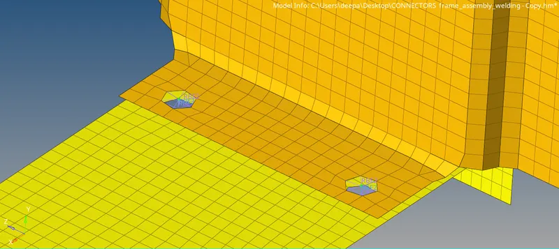
Fig: Bolt Connection
7) Right_Rail_1 & Right_Rail_2:- Spot-weld with Rigid Elements
- Select 1D/2D > Connectors > Spot option.
- Now select the location, where the Weld has to be created, by clicking the “node list”.
- Tick the checkbox of “retain nodes” option, to retain the position of the nodes, while creating and realizing a connector.
- Specify the “spacing” value and select the “comps” option under “connect what”, in order to create the weld between those two components.
- Select the number of layers(Number of Components) to be welded, under “num layers” option.
- Specify the “tolerance” value, based on the distance between the two components.
- Select the type as “rigid”.
- Click on the “create” button, to create the spot-weld wirh rigid elements.

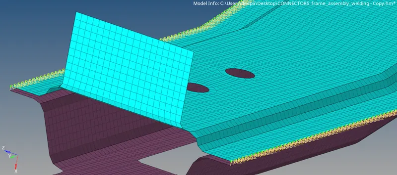
Fig: Spot-Weld With Rigid Elements Connection
8) Left_Rail_1 & Left_Rail_2:- Spot-weld with Spring Elements
- Select 1D/2D > Connectors > Spot option.
- Now select the location, where the Weld has to be created, by clicking the “node list”.
- Tick the checkbox of “retain nodes” option, to retain the position of the nodes, while creating and realizing a connector.
- Specify the “spacing” value and select the “comps” option under “connect what”, in order to create the weld between those two components.
- Select the number of layers(Number of Components) to be welded, under “num layers” option.
- Specify the “tolerance” value, based on the distance between the two components.
- Select the type as “spring”.
- Click on the “create” button, to create the spot-weld with spring elements.

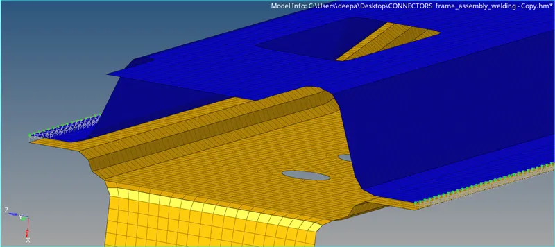
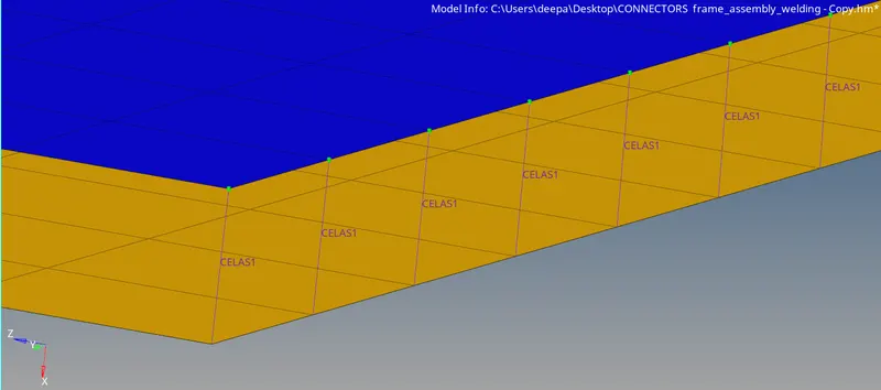
Fig: Spot-Weld With Spring Elements
9) Other Connections:-
Rear_Truss_1 & Rear_Truss_2:- RBE2 Elements
Go to 1D > rigids > independent - calculate node, dependent - multiple nodes > elem types - RBE2 > dof > create. Nodes are selected and elements are created seperately for both the holes and then select dependent - single node to create the bolt stem connecting dependent nodes of the both RBE2 elements with each other.


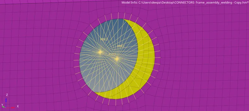
Fig: RBE2 Elements Connection
10) All the other connections are made with Seam-weld option.
- Select 1D/2D > Connectors > Seam option.
- Now select the location, where the Weld has to be created, by clicking the “node path”.
- Tick the checkbox of “retain nodes” option, to retain the position of the nodes, while creating and realizing a connector.
- Specify the “spacing” value and select the “comps” option under “connect what”, in order to create the weld between those two components.
- Specify the “tolerance” value, based on the distance between the two components.
- Select the type as “weld”.
- Click on the “create” button, to create the seam-weld.
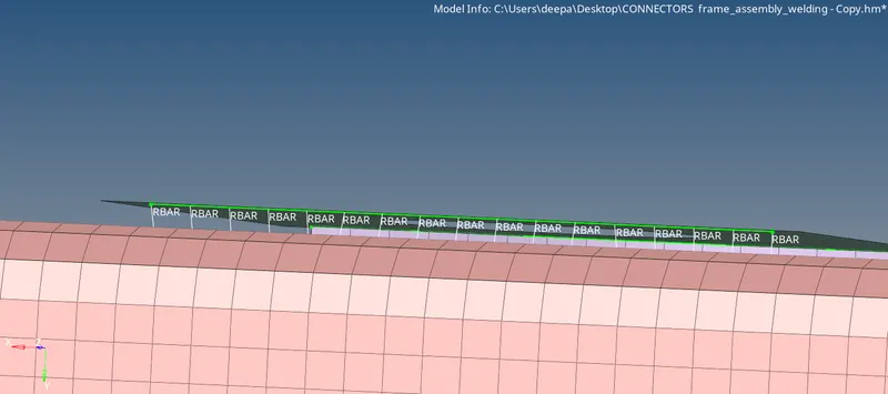
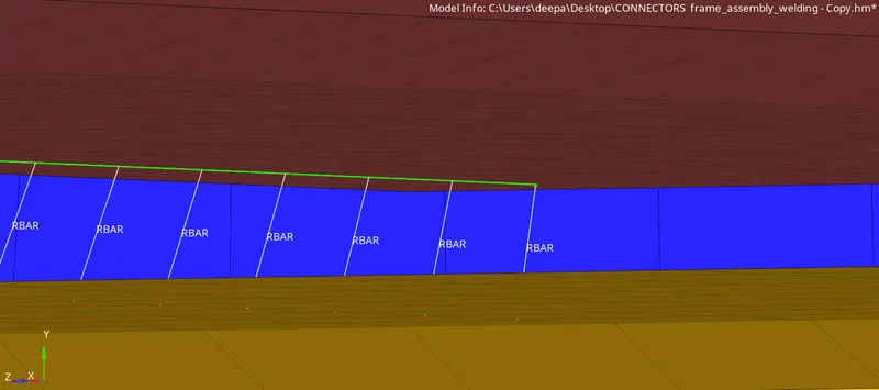
Fig: Seam-Weld Connection
Final model with connectors deployed:-
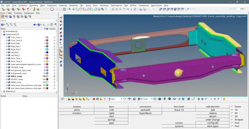
Fig: Final Meshed Model With All Connectors
RESULT:-
Successfully meshed the model given and also deployed connectors as per specified. Learned about different types of 1D connectors and their deployment.