Week 9-Creation of 1D Connectors Challenge
AIM:- To study the Creation of 1D Connectors with the help of HYPERMESH.
SOLVER:- Optistruct
OBJECTIVES:-
1. Importing the model.
2 . Creating mesh on the component within given quality criteria.
3. creating 1d connectors at their respective positions.
4. After connector creation fixing the failed elements.
PROCEDURE:-
A . Importing the geometry.
The geometry we are working on it. first, we are going to import to the hypermesh.
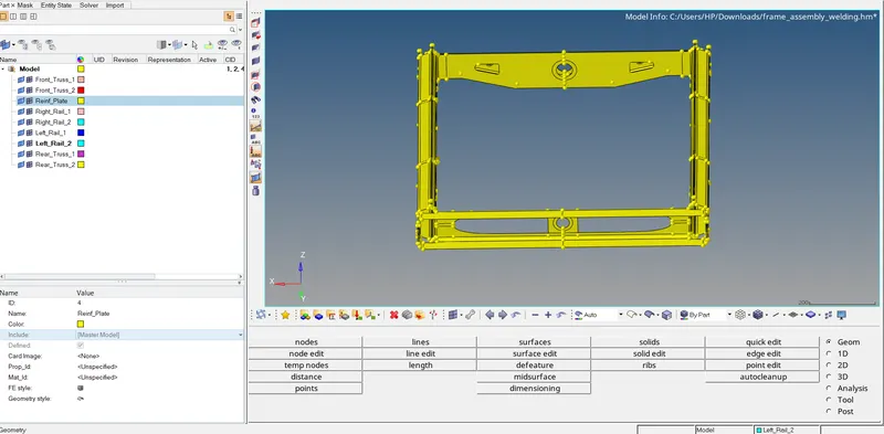
HOME>NEW>MODEL>IMPORT
the model will appear on the hypermesh window there are a total of 9 components into this assembly we need to join them with 1D connectors but before them, we need to mesh this component
B . Fixing the geometry
We will try to fix some areas where elements can be failed for quality criteria and also it will be easy to mesh.
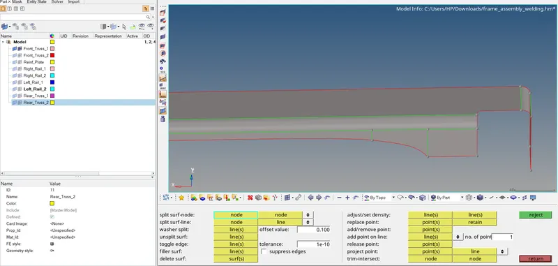
GEOMETRY>QUICK EDIT>SPLIT SURF-NODE>NODES(selecting the nodes)>ACCEPT(by pressing the middle mouse button)
we can use splitting the surface tool option where we can split the surface by constructing line for better mesh flow also we can toggle some lines which might be creating problems while meshing.
C. Setting up the quality criteria file.
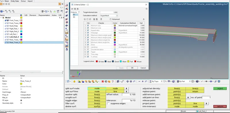
PREFERENCES>CRITERIA FILE SETTING>INPUT(putting all the given quality criteria given in the challenge)
under the 2d criteria table we are entering the given values whichever element going to exceed or below the given value will be failed and will be shown in the quality index.
D.Meshing the given component.
here we are using element size as 5 and mesh type as quad as it will be beneficial while creating 1d connectors as it will disturb the mesh flow
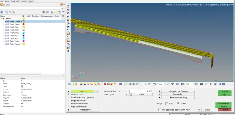
2D>AUTOMESH>SURF(selecting the surface)>ELEMENT SIZE(5)>MESH TYPE(QUADS)>MESH
to get better mesh we will be using a washer split around holes and also we can be adjusting the no elements and any other option which we can create a better mesh
E.Creating 1D connectors
Here the types of connectors are given and also their respective components in between we are going to connect them and also we are here using different types of connectors at different places so we can study their behaviors for our project and how these connectors are going to work.
These are given connectors and the particular types of them which we are going to use.
1. Right_Rail_2 & Front_truss_1:- Seam-Quad(angled+capped+L)
2. Left_Rail_2 & Front_truss_1:- Quad elements
3. Front_truss_2, Front_truss_1 & Right_Rail_1:- Spot weld with 2 Layers and 5 mm Diameter
4. Front_truss_2, Front_truss_1 & Left_Rail_1:- Hexa (Adhesive)
5. Rear_truss_2 & Right_Rail_2:- Bolt Connector
6. Rear_truss_2 & Left_Rail_2:- Bolt Connector
7. Right_Rail_1 & Right_Rail_2:- Spot-weld with Rigid Elements
8. Left_Rail_1 & Left_Rail_2:- Spot-weld with Spring Elements
9. Rest all the component left Join them with suitable connectors
1. Right_Rail_2 & Front_truss_1:- Seam-Quad(angled+capped+L)
First, we will visible the only components which we are going to connect in the component tree window which is Right_Rail_2 & Front_truss_1 and the connector type is Seam-Quad(angled+capped+L)
then we will select the location of the connector for which we are using nodelist and by selecting by path so we can create nodelist easily as it will save our time to select node one by one and as a reference for this certain seam connector we are choosing the location of the nodes on free edges.
after that changing the space value to 5 as our element size is 5 and select the components.
also giving the tolerance value so we can easily connect the two components easily and decide the type of connector as Seam-Quad(angled+capped+L) and other parameters as it is as there is no mention of weld angle and other angles we can change them if we want.
then clicking on realized and connector will be created and if not realized then we need to do certain changes
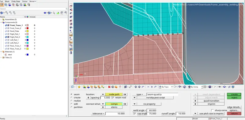
1D>CONNECTOR>SEA>LOCATION(NODES)>SPACING(which we are using according to our connector type>CONNECTION WHAT(two components we are going to connect>TOLERENCE(10.00)>TYPE(connector type as (Seam-Quad(angled+capped+L))>CREATE
RESULT:-
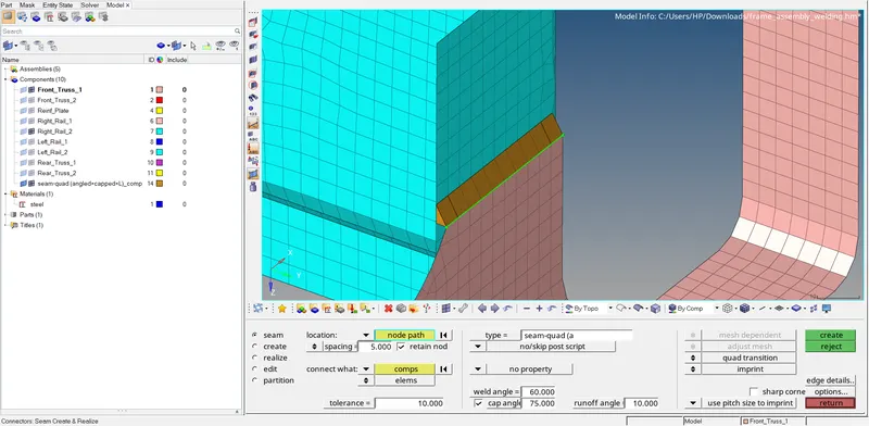
we can observe their seam weld connector is created between the two components and also the Seam.
Quad(angled+capped+L) as an individual component also gets created and property of it is also created.
2. Left_Rail_2 & Front_truss_1:- Quad elements
First, we will visible the only components which we are going to connect in the component tree window which is Left_Rail_2 & Front_truss_1 and the connector type is Quad elements.
then we will select the location of the connector for which we are using nodelist and by selecting by path so we can create nodelist easily as it will save our time to select node one by one and as a reference for this certain seam connector we are choosing the location of the nodes on free edges.
after that changing the space value to 1.
also giving the tolerance value so we can easily connect the two components easily and decide the type of connector as Seam (Quad elements) and other parameters as it is.
then clicking on realized and connector will be created and if not realized then we need to do certain changes.
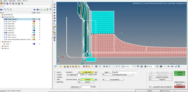
1D>CONNECTOR>SEA>LOCATION(NODES)>SPACING(which we are using according to our connector type>CONNECTION WHAT(two components we are going to connect>TOLERENCE(10.00)>TYPE(connector type as (Seam(Quad ELEMENTS))>CREATE
RESULT:-
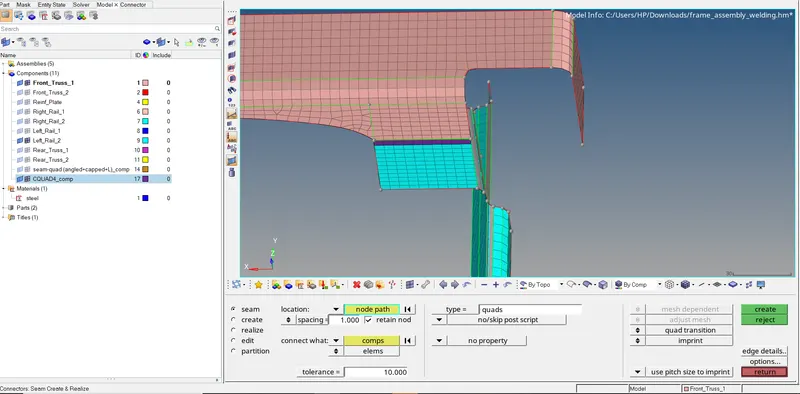
we can observe their seam weld connector is created between the two components and also the Seam Quad elements as an individual component get created and property of it is also created.
3. Front_truss_2, Front_truss_1 & Right_Rail_1:- Spot weld with 2 Layers and 5 mm Diameter
First, we will visible the only components which we are going to connect in the component tree window which is Front_truss_2, Front_truss_1 & Right_Rail_1 and the connector type is Spot weld with 2 Layers and 5 mm Diameter
then we will select the location of the connector for which we are using nodelist and by selecting by path so we can create nodelist easily as it will save our time to select node one by one and as a reference for this certain spot weld connector we are choosing the location of the nodes on arbitrary element not on free edges.
after that changing the space value to 5 as our element size is 5 and select the components which we are going to connect and no of the layer as 2 as we connect 2 components at one time or we can put no of layers as 3 so we can connect 3 at one time.
also giving the tolerance value so we can easily connect the two components and decide the type of connector as spot weld element and diameter as 5 mm we choose and other parameters as it is.
then clicking on realized and connector will be created and if not realized then we need to do certain changes.
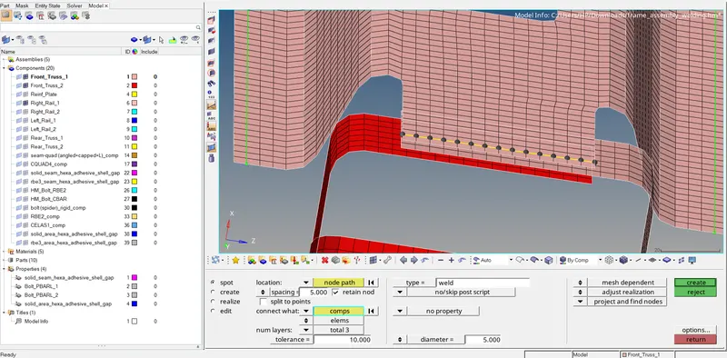
1D>CONNECTOR>SPOT>LOCATION(NODES)>SPACING(which we are using according to our connector type>CONNECTION WHAT(three components we are going to connect>number of layers (3)>TOLERENCE(10.00)>TYPE(connector type as (weld))>CREATE.
RESULT:-
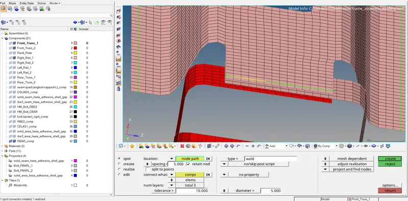
the realized connector indicates by the green line.
we can observe their spot weld connector is created between the two components and also the weld elements as an individual component also get created and property of it is also created.
4. Front_truss_2, Front_truss_1 & Left_Rail_1:- Hexa (Adhesive)
First, we will visible the only components which we are going to connect in the component tree window which is Front_truss_2, Front_truss_1 & Left_Rail_1 and the connector type is Hexa (Adhesive)
then we will select the location of the connector for which we are using nodelist and by selecting by path so we can create nodelist easily as it will save our time to select nodes one by one and as a reference for this certain type of seam weld connector we are choosing the location of the nodes on free edges or we can choose arbitrary element nodes.
after that changing the space value to 5 as our element size is 5 and select the components which we are going to connect and no of the layer as 2 as we connect 2 components at one time or we can put no of layers as 3 so we can connect 3 at one time.
also giving the tolerance value so we can easily connect the two components easily and decide the type of connector as Hexa adhesive under seam weld and other parameters as it is. which are like strips coats, shell gaps, and coats.
then clicking on realized and connector will be created and if not realized then we need to do certain changes.
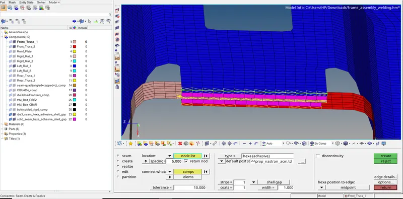
1D>CONNECTOR>SEAM>LOCATION(NODES)>SPACING(which we are using according to our connector type>CONNECTION WHAT(three components we are going to connect>number of layers (3)>TOLERENCE(10.00)>TYPE(connector type as (HEXA ADHESIVE)>CREATE.
RESULT:-
the realized connector indicates by the green line.
we can observe their Hexa adhesive connector is created between the three components and also the seam Hexa elements as an individual component get created and property of it is also created.
5. Rear_truss_2 & Right_Rail_2:- Bolt Connector
First, we will visible the only components which we are going to connect in the component tree window which is Rear_truss_2 & Right_Rail_2 and the connector type is Bolt Connector.
then we will select the location of the connector for which we are using nodelist and by selecting by path so we can create nodelist easily as it will save our time to select nodes one by one and as a reference for this certain type of bolt connector (CBAR) we are choosing the location of the nodes on free edges or we can choose arbitrary element nodes as here we are creating bolts we are going any two arbitrary node as we using as bolt center point.
after that changing the space value to 5 as our element size is 5 and select the components which we are going to connect
also giving the tolerance value so we can easily connect the two components easily and decide the type of connector as BOLT CBAR and also here we are selecting the option as creating a hole if none as the location we are accessing has no holes to connect bolt we are creating a hole the element on the surface are disturbing the mesh flow and also failed so we need to fix them.
then clicking on realized and connector will be created and if not realized then we need to do certain changes.
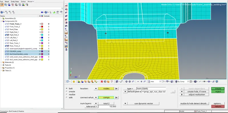
1D>CONNECTOR>BOLT>LOCATION(NODES)>SPACING(which we are using according to our connector type>CONNECTION WHAT(three components we are going to connect>TOLERENCE(10.00)>TYPE(connector type as (Bolt CBAR)>CREATE.
RESULT:-
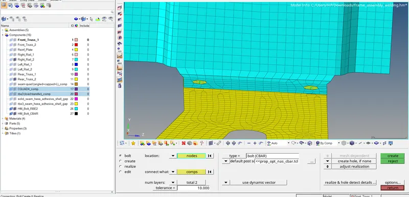
the realized connector indicates by the green line.
we can observe their BOLT connector is created between the two components and also the bolt cbar as an individual component also get created and its property also created.
6. Rear_truss_2 & Left_Rail_2:- Bolt Connector
First, we will visible the only components which we are going to connect in the component tree window which is Rear_truss_2 & Right_Rail_2 and the connector type is Bolt Connector.
then we will select the location of the connector for which we are using nodelist and by selecting by path so we can create nodelist easily as it will save our time to select nodes one by one and as a reference for this certain type of bolt connector (CBAR) we are choosing the location of the nodes on free edges or we can choose arbitrary element nodes as here we are creating bolts we are going any two arbitrary node as we using as bolt center point.
after that changing the space value to 5 as our element size is 5 and select the components which we are going to connect
also giving the tolerance value so we can easily connect the two components easily and decide the type of connector as BOLT CBAR and also here we are selecting the option as creating a hole if none as the location we are accessing has no holes to connect bolt we are creating a hole as we are creating a hole the element on the surface are disturbing the mesh flow and also failed so we need to fix them.
then clicking on realized and connector will be created and if not realized then we need to do certain changes.
1D>CONNECTOR>BOLT>LOCATION(NODES)>SPACING(which we are using according to our connector type>CONNECTION WHAT(three components we are going to connect>TOLERENCE(10.00)>TYPE(connector type as (Bolt spider)>CREATE.
RESULT:-
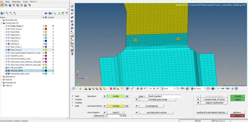
the realized connector indicates by the green line.
we can observe their BOLT connector is created between the two components and also the bolt spider element as an individual component gets created and its property is also created automatically.
7. Right_Rail_1 & Right_Rail_2:- Spot-weld with Rigid Elements
First, we will visible the only components which we are going to connect in the component tree window which is Right_Rail_1 & Right_Rail_2 and the connector type is Spot-weld with Rigid Elements.
then we will select the location of the connector for which we are using nodelist and by selecting by path so we can create nodelist easily as it will save our time to select node one by one and as a reference for this certain spot weld connector we are choosing the location of the nodes on arbitrary element not on free edges.
after that changing the space value to 5 as our element size is 5 and select the components which we are going to connect and no of the layer as 2 as we connect 2 components at one time.
also giving the tolerance value so we can easily connect the two components easily and decide the type of connector as spot weld with rigid element and we choose and other parameters as it is.
then clicking on realized and connector will be created and if not realized then we need to do certain changes.
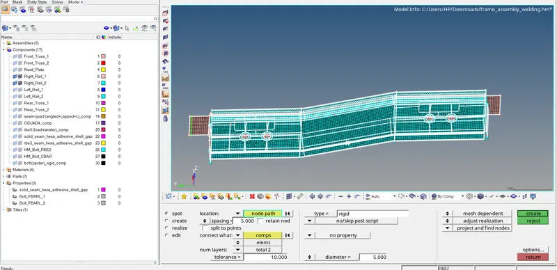
1D>CONNECTOR>SPOT>LOCATION(NODES)>SPACING(which we are using according to our connector type>CONNECTION WHAT(two components we are going to connect>number of layers (2)>TOLERENCE(10.00)>TYPE(connector type as (Rigid ))>CREATE.
RESULT:-
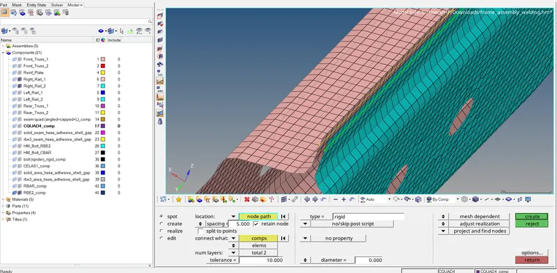
same we are doing on either side of components as they also need to be connected.
the realized connector indicates by the green line.
we can observe their spot weld rigid elements connector is created between the two components and also the spot weld as rigid element individual component also get created and its property also created.
8. Left_Rail_1 & Left_Rail_2:- Spot-weld with Spring Elements
First, we will visible the only components which we are going to connect in the component tree window which is Left_Rail_1 & Left_Rail_2 and the connector type is Spot-weld with Spring Elements.
then we will select the location of the connector for which we are using nodelist and by selecting by path so we can create nodelist easily as it will save our time to select node one by one and as a reference for this certain spot weld connector we are choosing the location of the nodes on arbitrary element not on free edges.
after that changing the space value to 5 as our element size is 5 and select the components which we are going to connect and no of the layer as 2 as we connect 2 components at one time.
also giving the tolerance value so we can easily connect the two components easily and decide the type of connector as spot weld with spring elements and we choose and other parameters as it is.
then clicking on realized and connector will be created and if not realized then we need to do certain changes.
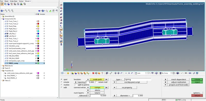
1D>CONNECTOR>SPOT>LOCATION(NODES)>SPACING(which we are using according to our connector type>CONNECTION WHAT(two components we are going to connect>number of layers (2)>TOLERENCE(10.00)>TYPE(connector type as (spring element ))>CREATE.
RESULT:-
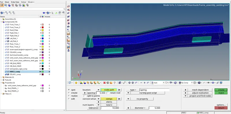
same we are doing on either side of components as they also need to be connected.
the realized connector indicates by the green line.
we can observe their spot weld rigid elements connector is created between the two components and also the spot weld as spring element individual component also get created and its property also created automatically.
9 Front_truss_2, Front_truss_1 & Reinf plate :- Area (adhesives)
First, we will visible the only components which we are going to connect in the component tree window which is Front_truss_2, Front_truss_1 & Reinf plate and the connector type is Area adhesives.
then we will select the location of the connector for which we are using nodelist and by selecting by path so we can create nodelist easily as it will save our time to select node one by one and as a reference for this certain Area adhesives connector we are choosing the location of the nodes on free edges.
keeping the width and offset value as it is because we don't have any given value.
selecting the components which we are going to connect and no of the layer as 2 as we connect 2 components at one time.
also giving the tolerance value so we can easily connect the two components easily and decide the type of connector as Area adhesives and we choose and other parameters as it is.
then clicking on realized and connector will be created and if not realized then we need to do certain changes.
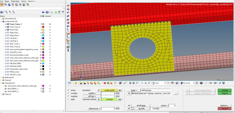
1D>CONNECTOR>AREA>LOCATION(NODES)>Width>Offset>CONNECTION WHAT(two components we are going to connect>TOLERENCE(10.00)>TYPE(connector type as (Adhesives))>CREATE.
RESULT:-
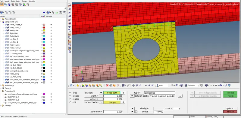
and we are going to do that on either side as we connect front truss 1 and refine plate similar front truss 2 and reinf plate
the realized connector indicates by the green line.
we can observe their spot weld rigid elements connector is created between the two components and also the Area as adhesives individual component also get created and its property created automatically.
10.Left_Rail_1 & Rear_truss_2 :- Seam (QUADS)
First, we will visible the only components which we are going to connect in the component tree window which is Left_Rail_1 & Rear_truss_2 and the connector type is Seam (QUADS).
then we will select the location of the connector for which we are using nodelist and by selecting by path so we can create nodelist easily as it will save our time to select node one by one and as a reference for this certain seam connector we are choosing the location of the nodes on free edges.
after that changing the space value to 5.
also giving the tolerance value so we can easily connect the two components easily and decide the type of connector as Seam (Quad elements) and other parameters as it is.
then clicking on realized and connector will be created and if not realized then we need to do certain changes.
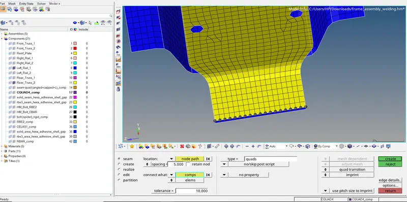
1D>CONNECTOR>SEA>LOCATION(NODES)>SPACING(which we are using according to our connector type>CONNECTION WHAT(two components we are going to connect>TOLERENCE(10.00)>TYPE(connector type as (Seam(Quad ELEMENTS))>CREATE.
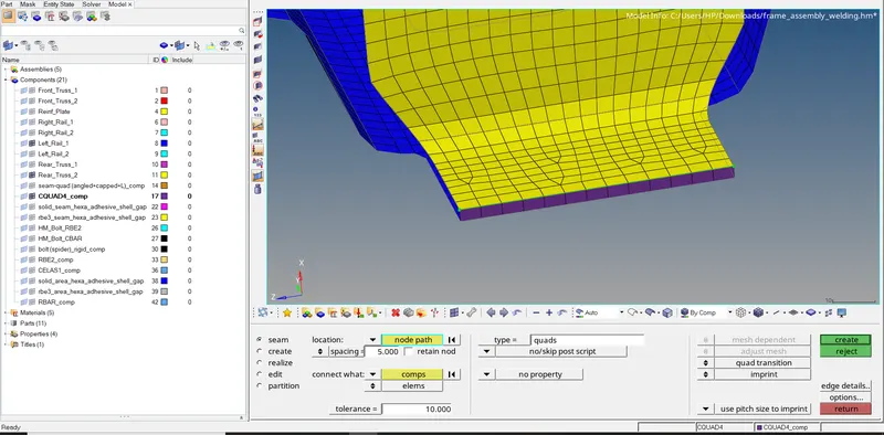
and we are going to do that on either side as we connect Left_Rail_1 & Rear_truss_2
the realized connector indicates by the green line.
we can observe their spot weld rigid elements connector is created between the two components and also the spot weld as spring element individual component also get created and its property also created automatically.
F.Creating materials and Assigning properties:-
As we already have components in the tree window we need to create properties for them as we want to assign different properties for them including thickness
so we add an individual property for an individual component and in the component section we right-click on that particular component and assign its appropriate property here our objective is not to create properties but to create connectors will be only assigning thickness values
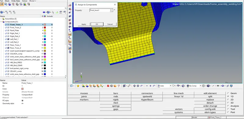
also, we are using steel as the only material for all the components to avoid complexity in the project.
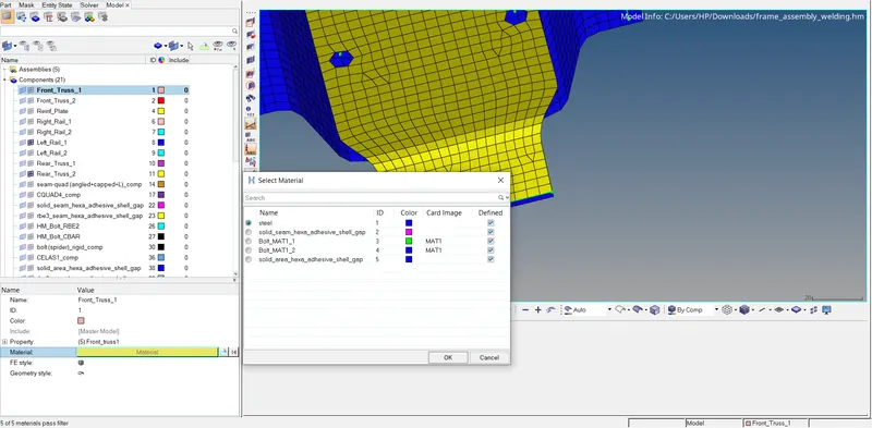
For connectors:-
and in the case of connector as we create a connector hypermesh automatically create property and material for the connector
G.QUALITY INSPECTION:-
we will move to the quality index tool and visible ball the components one by one we can see either element are failing or not because of connectors are disturbing mesh flow so we will fix them with re-mesh or element cleanup method and it is important to that as connector works help to transfer whatever force acts on the element of one component to element on another component. connector keep them connected.
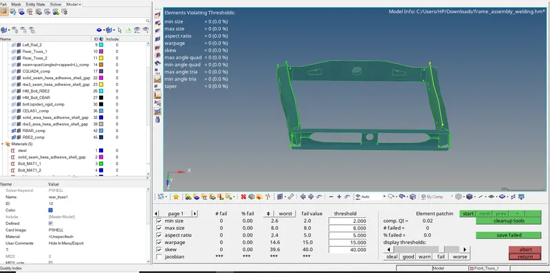
As here we can see zero elements are failing for quality criteria which we set so we accept our model which we perform for creating a 1D connector.
FINAL RESULT:
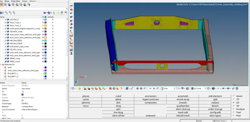
also if we want to observe the connectors separately we can hide the respective components from the tree window.
CONCLUSIONS:
1. We study how to mesh our component with given quality criteria and create a 1d connector to connect the components and also fix the elements which are disturbing after creating connectors.