Week 9-Creation of 1D Connectors Challenge
OBJECTIVE:
Mesh the geometry by following the stipulated quality parameters and create connectors to attach the various parts of the given model.
PROCEDURE:
- Firstly, the model is imported into Hyperworks 2020 and a save file is created to save any further progress.
- The imported model appears as indicated.
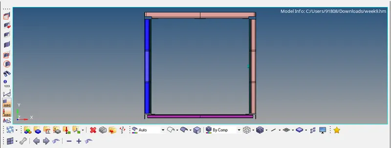
- Next, auto cleanup is performed after editing element criteria for the suitable cleanup based on element sizes using the "Geometry | Autocleanup" option.
- The components after auto cleanup are depicted, containing some suppressed lines and some unsuppressed lines.
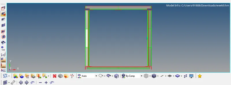
- Going further, before meshing the geometry, any manual suppressing or unsuppressing of lines is performed to obtain a well-defined mesh. This can be done using the "Geometry | Quick Edit | Toggle edge" or using the "Geometry | Edge edit | Toggle" options.
- By manually performing this step, we eliminate some errors of minimum element sizes. At times, extra lines are defined to mesh the components one half at a time for better control by using the tools in the "Geometry | Quick Edit" feature.
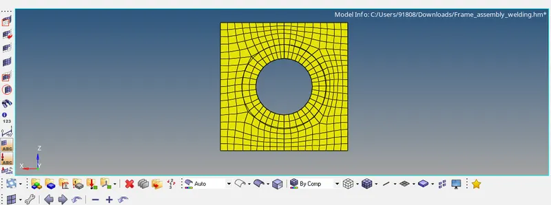
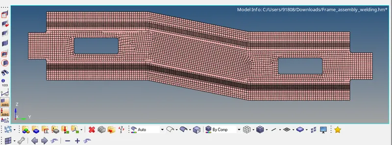
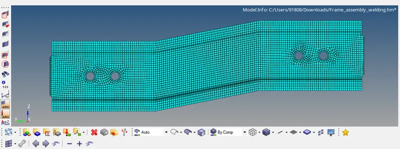
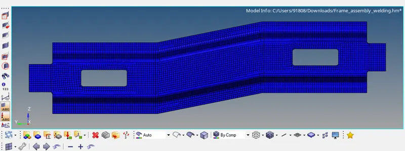
- Moving forward, each of the components is separately meshed using the "2D | Automesh" feature by choosing the element type and the target element length of 5mm. The obtained mesh will require some fine-tuning. This can be done by the "Tool | Check elems | 2-D" and "2D | Quality check" options. Elements can be re-meshed in the "2D | Automesh" or the "2D | Rebulid mesh" features.
- The objective of the meshing process is to obtain as low a number of rotational quads and tria elements as possible. This process is repeated for all the different components. Some of the components possess a simple line of symmetry. Alternatively, these components can be cut in half, meshed and then mirrored using the "Tools | Reflect" option and then equivalenced using the "Tools | Edges | Equivalence" option.
- Meshed components are portrayed underneath.
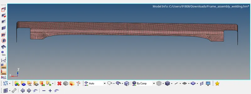
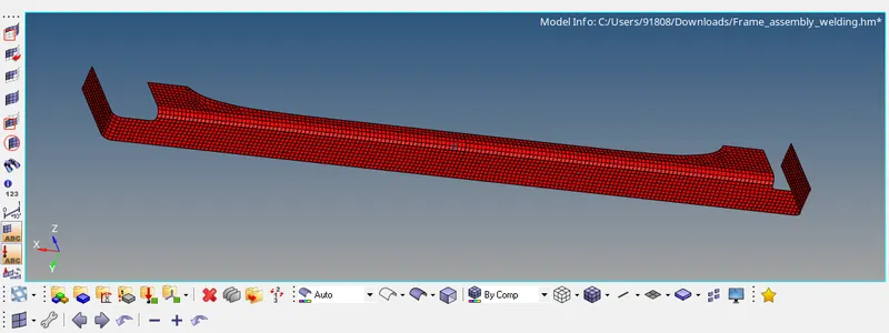
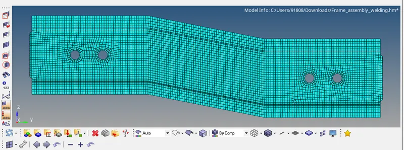
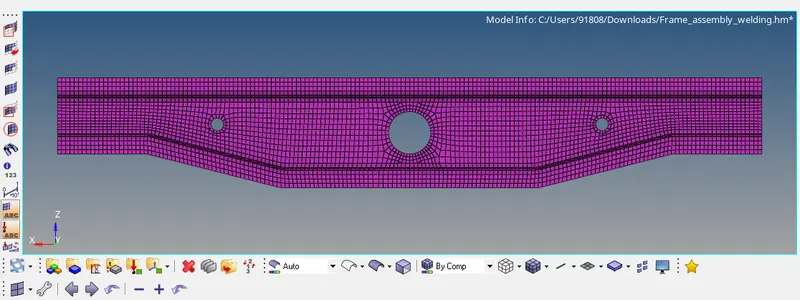
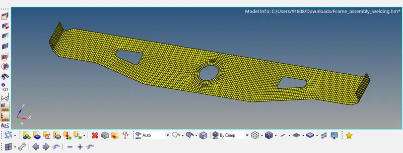
- Now that we have a defined mesh for each of our components, the components have to be connected to each other to act as one mechanical system. These connections are defined based on the application.
- Most connections are built as specified by using the "2D | Connectors" option and by specifying the proper spacing, tolerance and type of connector.
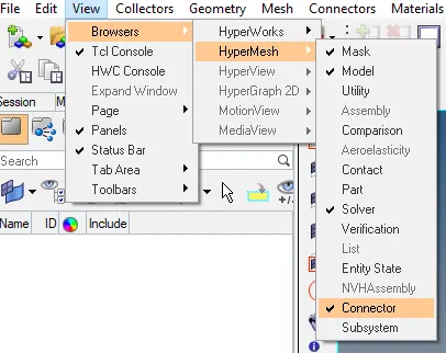
- At times, certain connectors can be highlighted in red after being built. These are failed connectors and have to be realized individually by using the "View | Browser | HyperMesh | Connector" option. The fault is most often with the tolerance, spacing or angles, in some cases.
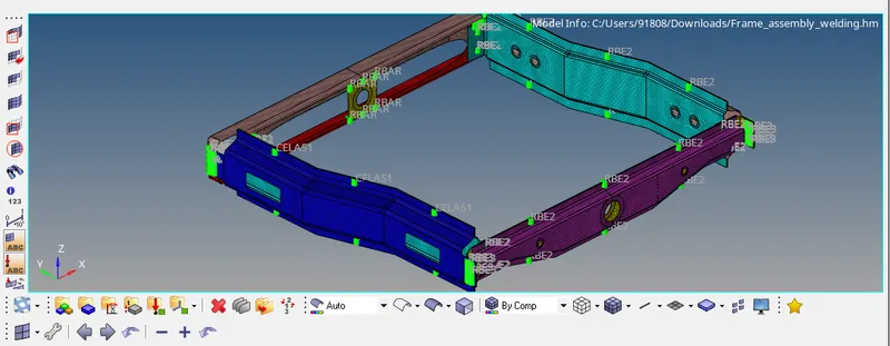
- The specified connectors are shown below.
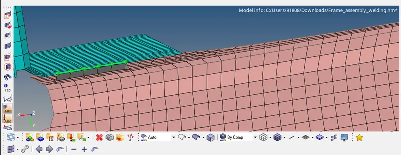
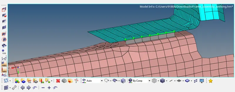
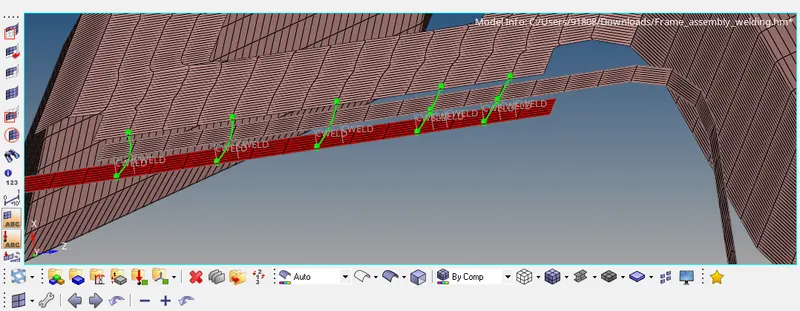
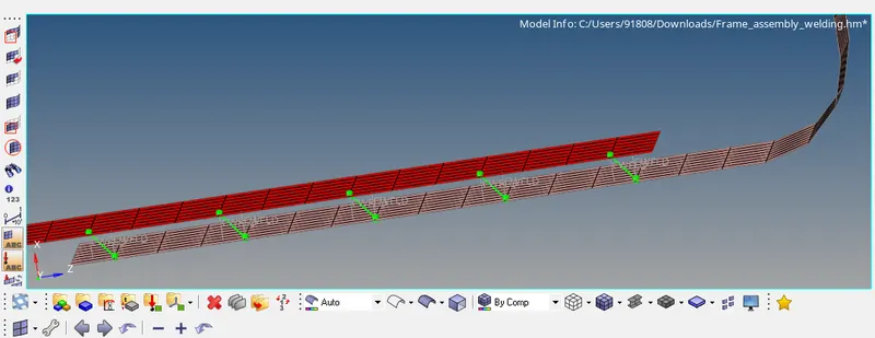
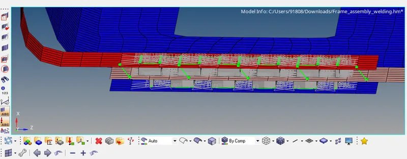
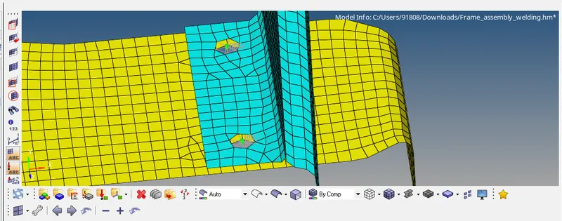
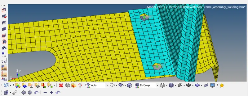
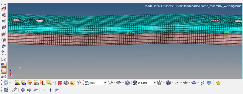
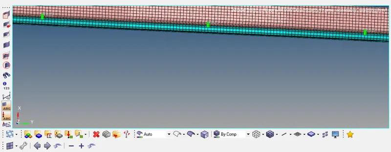
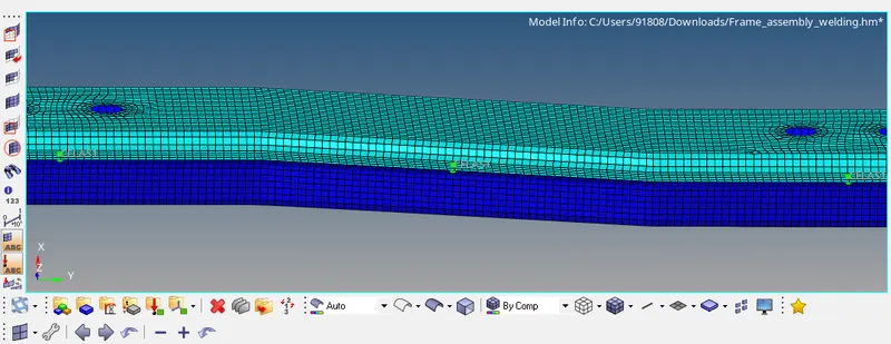
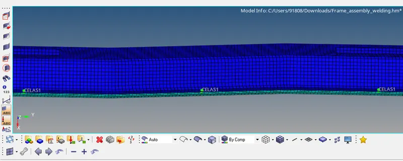
- If any part of the geometry is left unconnected, this becomes an issue with its working and its analysis, under loading conditions. Thus, some of the connections which have remained not connected are connected using the same features as explained previously.
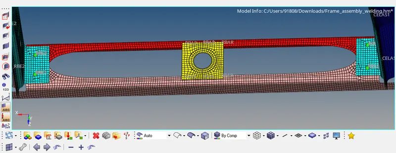
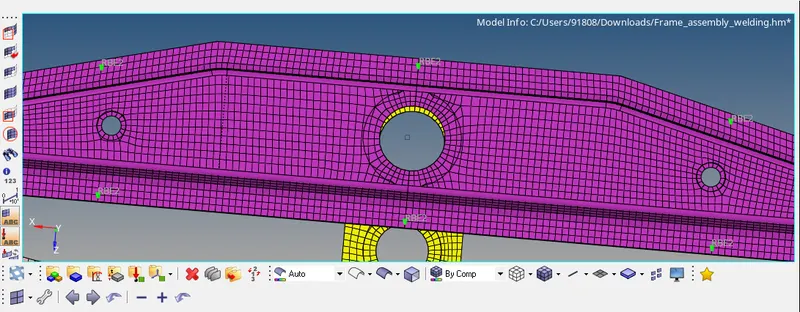
- The final model with appropriate quality mesh and connections is depicted below.
RESULT:
Given model is meshed according to quality criteria and appropriate connections are defined.