Week 4- Challenge
OBJECTIVE:
To create 1D elements on the given model with given cross-section and DOF.
PROCEDURE:
- Firstly, the geometry is imported into Hypermesh 2020 and auto clean is performed to correct dimensional irregularities and discontinuities.
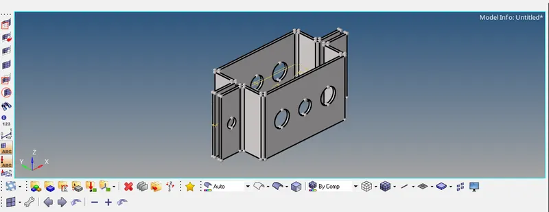
- The imported model is as shown below:
- Midsurfaces are extracted from both the upper and lower halves of the model (while noting the thickness of each half of the geometry) after which, the property and material data are added to each of the midsurfaces. Subsequently, the solids are deleted as they are no more significant.
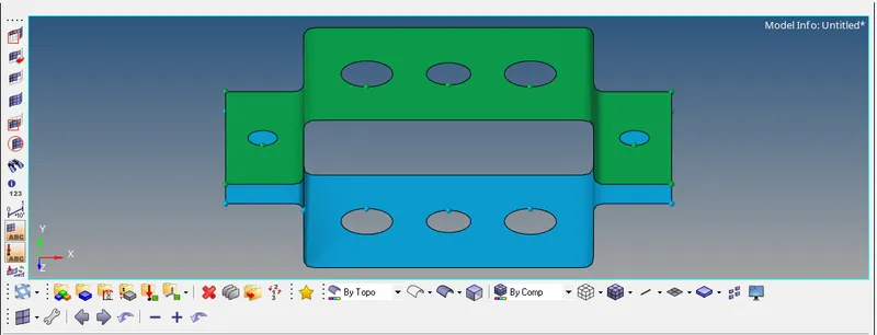
- The extracted midsurfaces are depicted below.
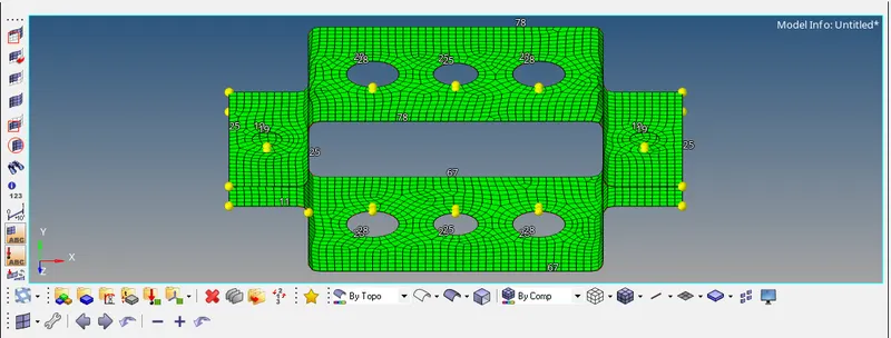
- Before heading towards the RBE2 and RBE3 links, a thorough mesh is performed by automesh. Then, some features of the mesh are corrected manually for a better mesh quality. A washer split is created near holes to ensure uniformity of mesh.
- In the example shown, an element size of 5mm is chosen for good mesh accuracy and optimal computing time.
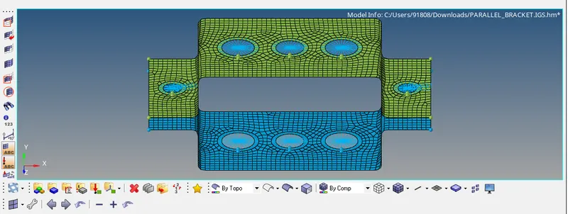
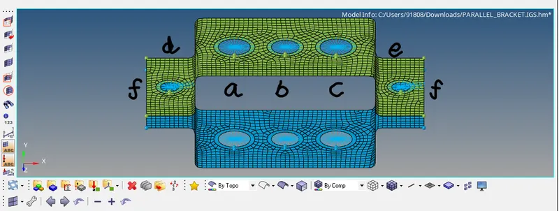
- Going further, RBE2 links are assigned to the bottom two holes (d and e) of both halves and on the leftmost hole (a) of both halves where the spring elements (f) and the rod element are created respectively.
- Moving on, RBE3 elements are created in the middle (b) and the right holes (c) of both plates where the beam and bar elements are created respectively.
- Next, a mass of magnitude 10 is assigned to the RBE2 links created at d and e using the CMASS1 element.
- The below images show the created RBE2, RBE3 and CMASS1 links. The figure to the right explains the letters a, b, c, d, e and f and is not a visual aid of the software used.
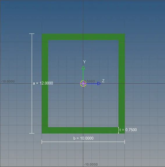
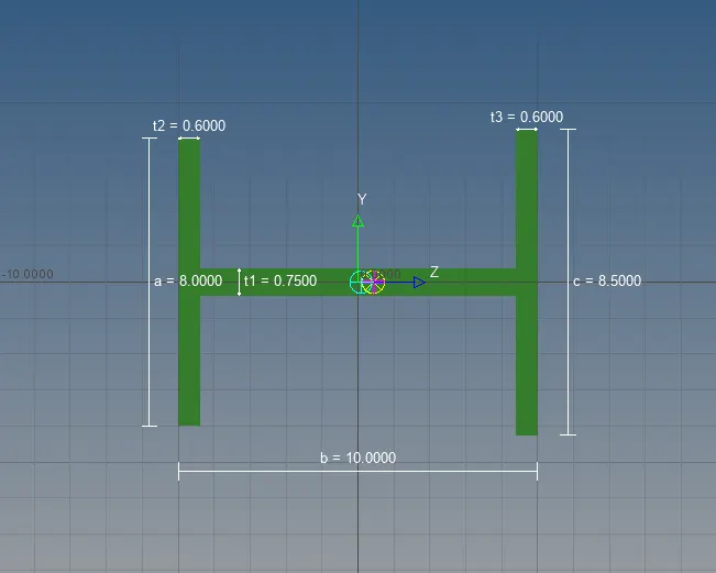
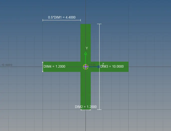
- Further on, a rod element of "box" section, a beam element of "I" section and a bar of "cross" section are created using the Hyperbeam window with the given measurements as indicated. All these elements are 1D elements as their magnitude along one axis (in this case, Y-axis) is tremendously higher than the magnitudes about the other two axes.
- The spring element (f) (also a 1D element) is then designated to the area where a mass of a magnitude of 10 was previously indicated (d and e).
- The elements are now assigned details of their properties and material.
- The picture below shows the representation of these elements.
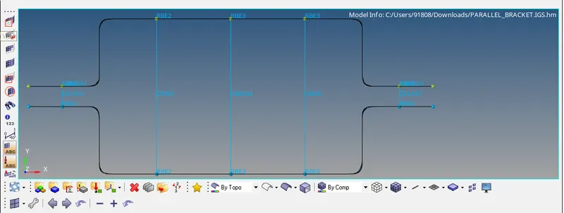
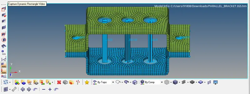
- Finally, the elements are created as shown below. Please note that a detailed view of both 1D and 2D features is chosen for a clear view of the features created.
RESULT:
1D elements of four different types (bar, rod, beam and spring) are created on the given geometry using the Hyperbeam feature and the given challenge has been completed.