Assignment 1-2D Meshing Challenge
AIM :- Create 2D mesh for given components by considering below rules.
- There should not be any free edges, convert all of them into refine geometry.
- Clean the geometry.
- Extract midsurface.
- Clean midsurface geometry.
- Ignore holes less than dia 5mm.
- Create 2D mesh with target length 5mm, min 3.5mm max 7mm.
- And assign proper thickness, by creating a generic property.
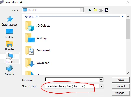
- Save in .hm format.
Procedure :-
- Import given .hm file into hypermesh , go to import model - select file - click on import
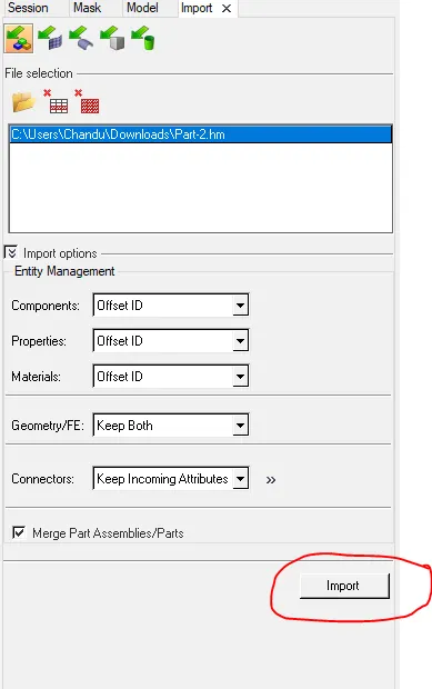
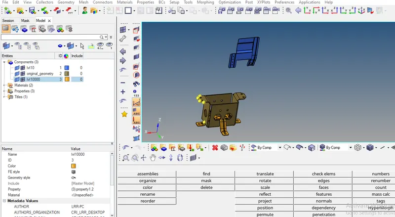
- Follow the above mentioned path, to import remaining all components, click on fit model option , to fit all components in single window
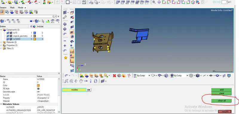
- Remove all temporary nodes present in model , go to geom - temp nodes - clear all
- before doing meshing , we have to do geometry cleanup
- there are 3 components in input, so do geometry cleanup one by one
lvl 10 :-
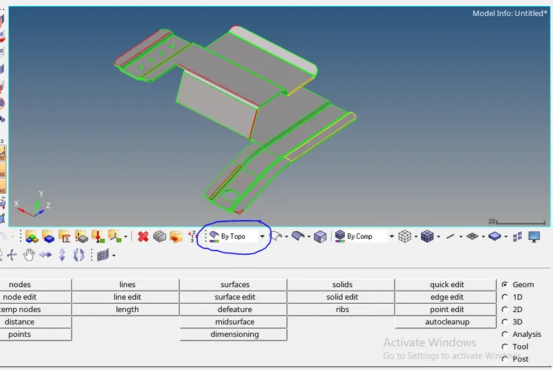
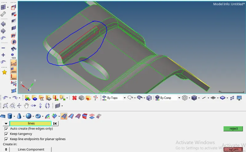
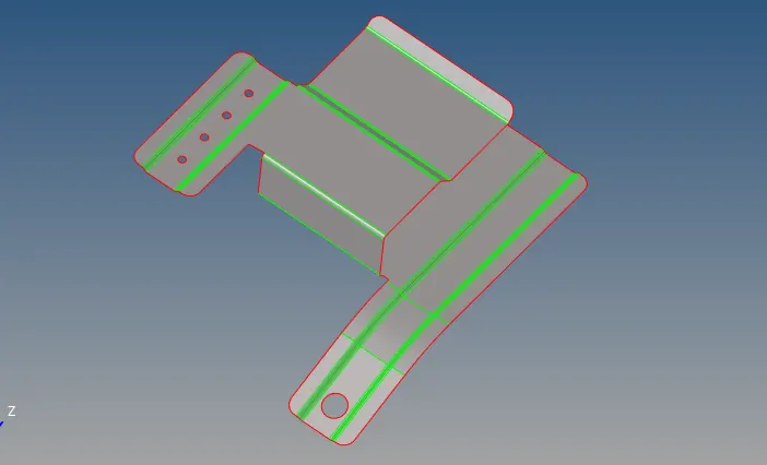
- To check connectivity errors put it in By Topo view mode
- in the above pic we can see some green lines , red lines and yellow lines
- green lines means both surfaces are connected properly without any fail
- red lines means there is an error(gap) between surfaces or missing surface
- yellow lines means three or more surfaces connected or duplicate surfaces
- by using quick edit, surfaces, surface edit options we can clear this topology errors mostly toggle edge and replace point options are used
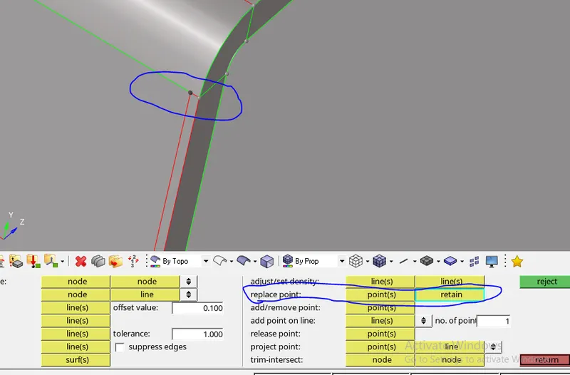
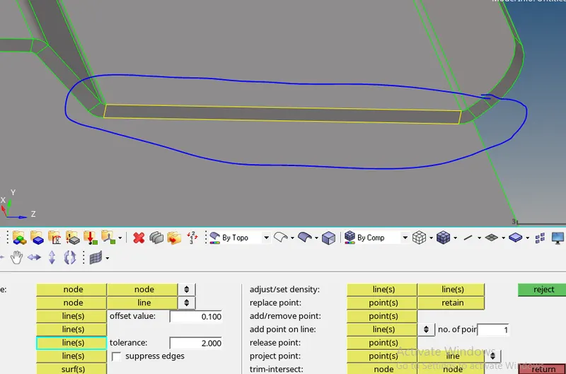
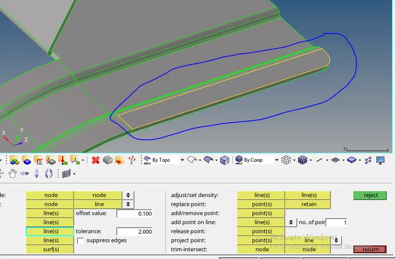
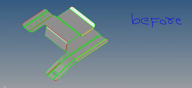
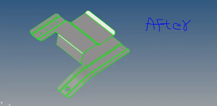
- Put in wire frame view mode , to see all surfaces are connected properly or not
-
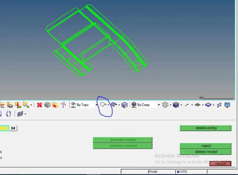
- After that extract the mid surface , go to geom - mid surface -select surfaces - click on extract
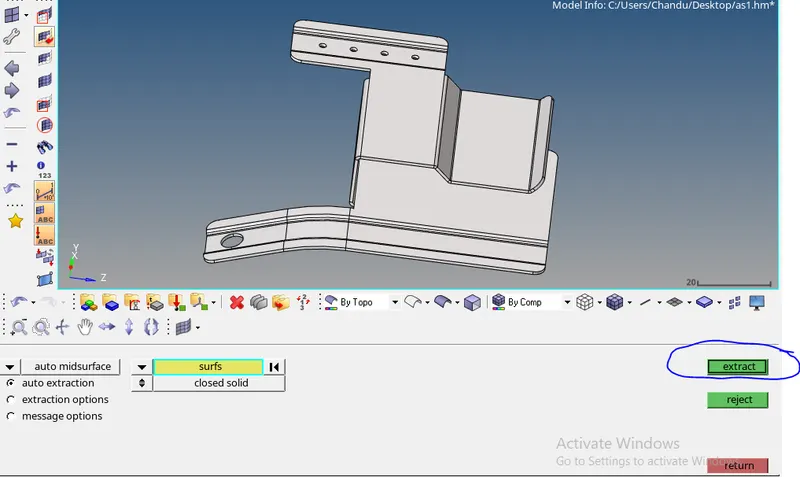
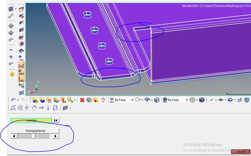
- To check whether generated auto mid surface correct are not , put parent component in transparent mode
-
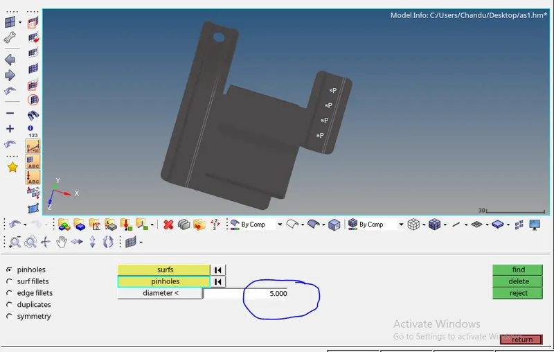
- defeature pin holes which are <5mm in dia , go to geom - defeature- pin holes - select surfaces - give diameter - click on find - click on delete
- defeature surface fillets which are less than min element size , go to geom - defeature- surface fillets- select surfaces - give parameters - click on find - click on remove.
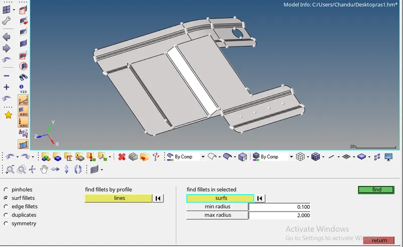
- Now do meshing operation, go to - 2D- automesh - select surface - give element size (5mm) - element type (mixed) - click on mesh
-
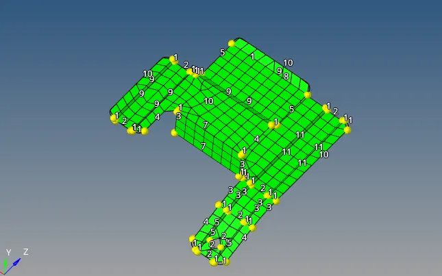
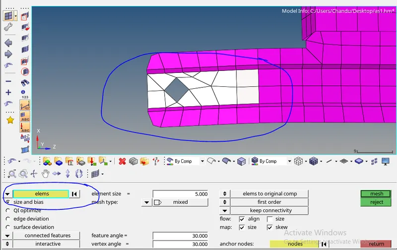
- some elements are not captured the features properly so remesh at that location
-
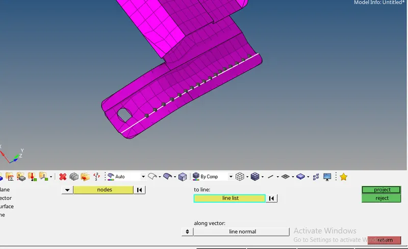
- project all elements nodes on surface edge using proect option , go to - tools - project- to line - select nodes (using by path option) - select line - click on project
- after meshing go for quality check , to set quaity parameters , go to preferences - criteria file settings
-
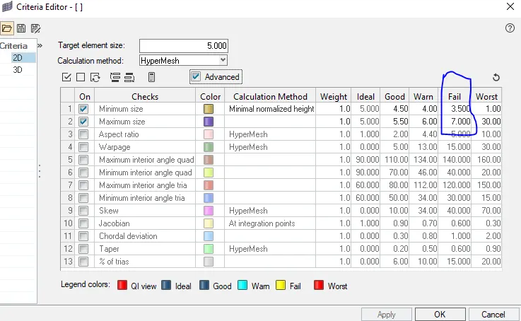
- To check elements quality go to 2D- Quality index
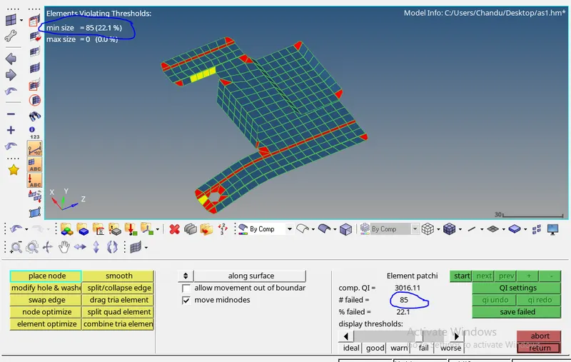
- from the above pic , it shows 85 elements are failing for quality
- most of the elements failing at corners because , length of the edge is too small when compared with min element size, to check its length press F4
-
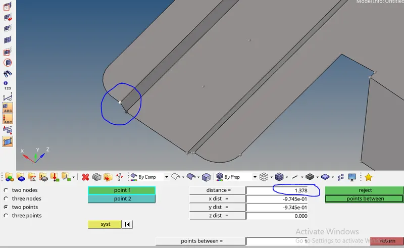
- to solve this supress its one of the edge , go to geom - quick edit - toggle edge (OR) go to geom - edge edit - supress edge.
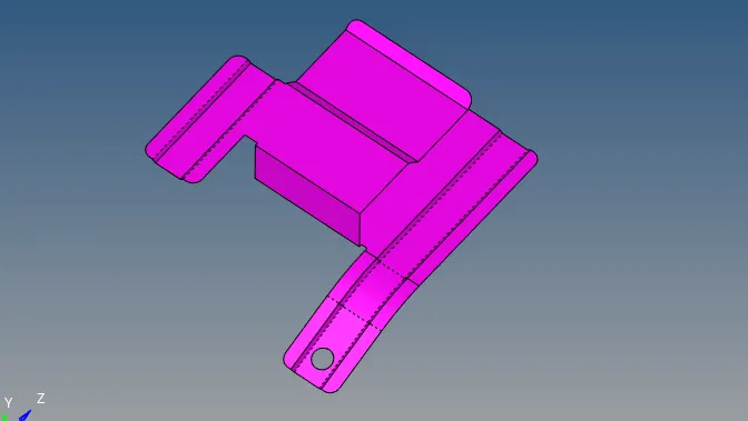
- Use cleanup tools , edit element , replace , node edit , smooth ,remesh options to clear the quality check for remaining elements
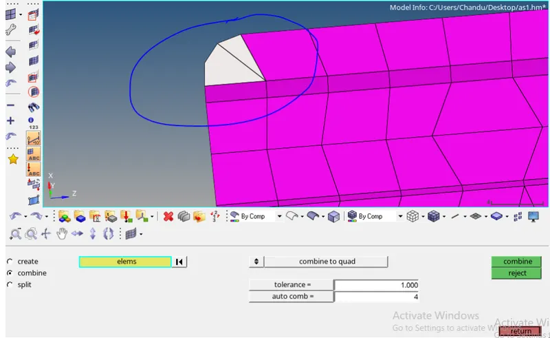
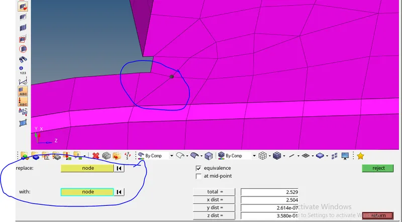
-
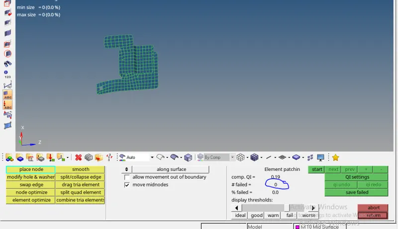
- Above pic shows all elements are cleared quality check.
lvl 10000:-
- extract mid surface , go to geom - mid surface -select surfaces - click on extract
-
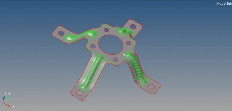
- toggle the unnecssary edges , go to geom- quick edit - toggle edge
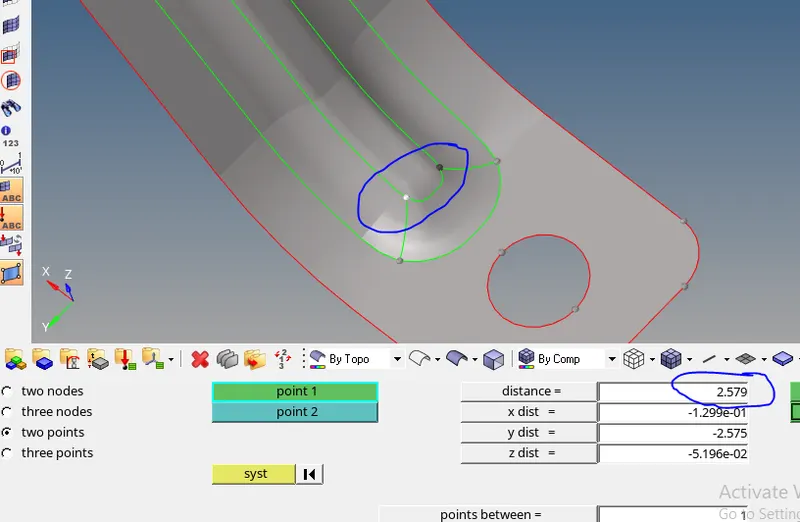
- in the above pic , it shows distance between two points are less than min element size , so supress those edges also
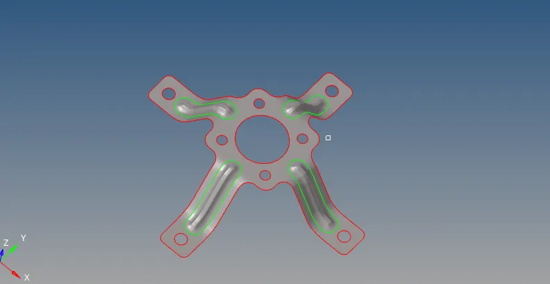
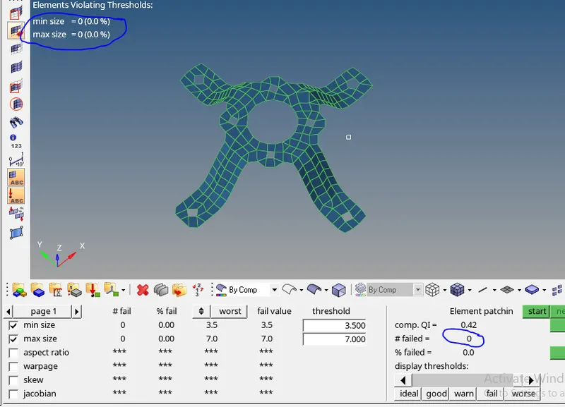
- after completed geometry clean up go for 2D Meshing, go to - 2D- automesh - select surface - give element size (5mm) - element type (mixed) - click on mesh
- To clear quality check , follow the procedure for above mntioned lvl 10 component
-
original geometry :-
- extract mid surface , go to geom - mid surface -select surfaces - click on extract
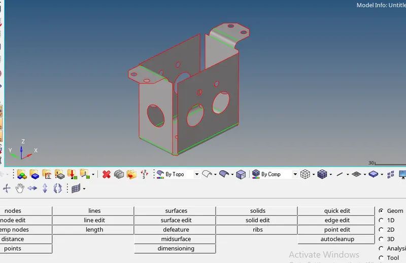
- defeature pin holes which are <5mm in dia , go to geom - defeature- pin holes - select surfaces - give diameter - click on find - click on delete
- defeature surface fillets which are less than min element size , go to geom - defeature- surface fillets- select surfaces - give parameters - click on find - click on remove
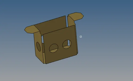
- after completed geometry clean up go for 2D Meshing ,go to - 2D- automesh - select surface - give element size (5mm) - element type (mixed) - click on mesh
- To clear quality check , follow the procedure for above mntioned lvl 10 component
-
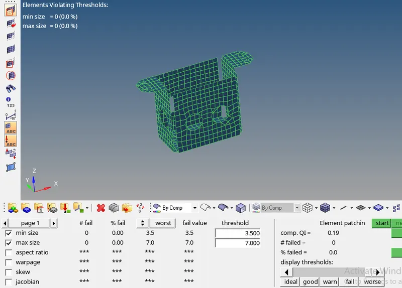
- after meshing crate thickness to the elements
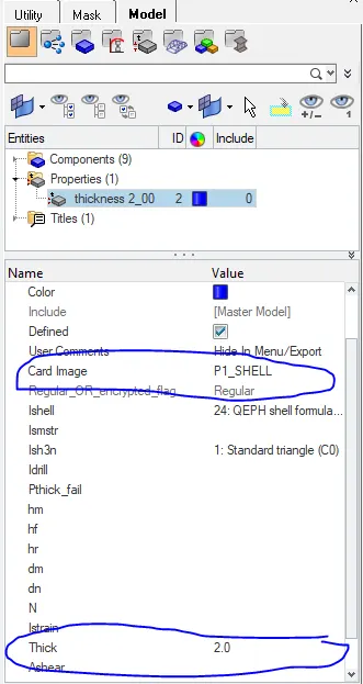
- create a new property , right click - create - proprty , rename the property into thickness 2_00
- select card image - P1_SHELL , and give Thick 2.00
-
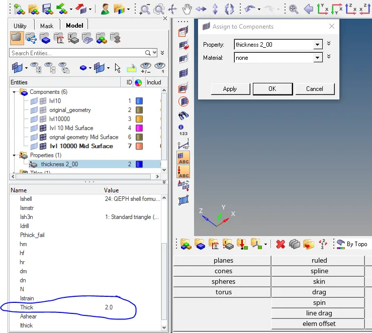
- after creating property assign this property to elements
- select component - right click- assign - select property - click on ok
RESULT :-
- Check free edges for elements , go to tools - edges - select elements - tolerence (0.1) - find edges
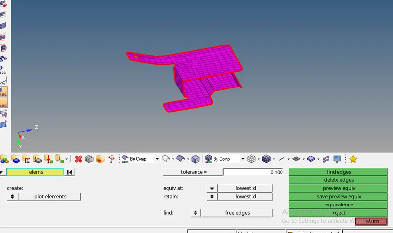
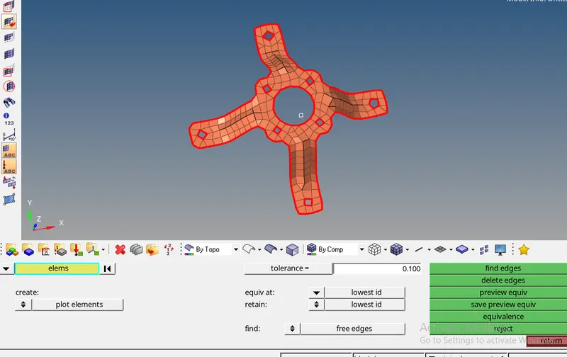
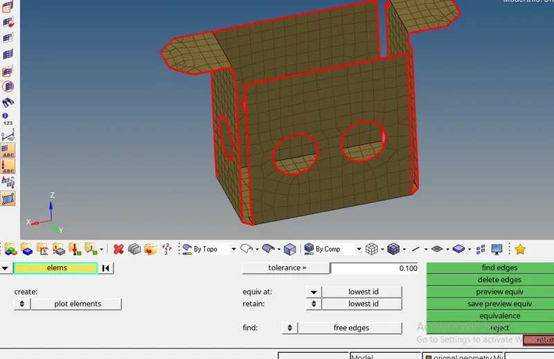
- all elemenents are conncted properly without any gap.
- To whether thickness is assigned or not , put elements in 2D Detailed Element Representation mode and By Prop mode
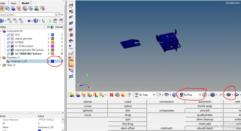
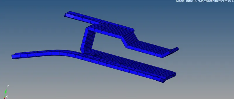
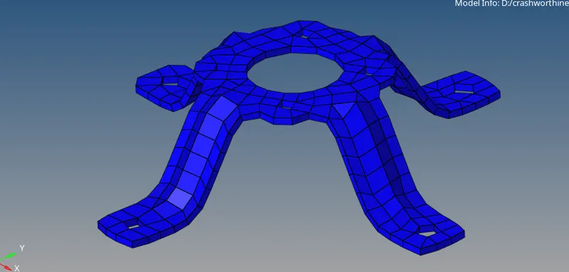
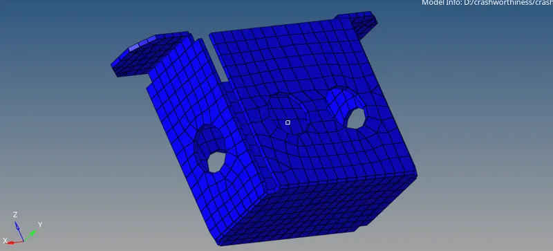
- save the model in .hm format , go to file - save as