Week 9-Creation of 1D Connectors Challenge
Connectors in Hyper Mesh
Aim
To mesh the given model according to given criteria and create connections as required.
Procedure
- Criteria for mesh quality is given in table1.
|
S.N |
Quality Criteria |
Value |
|
1 |
Aspect Ratio |
5 |
|
2 |
Skewness |
45 |
|
3 |
Warping |
15 |
|
4 |
Taper |
0.5 |
|
5 |
Min. Length |
2 Units |
|
6 |
Max. Length |
8 Units |
|
7 |
Min angle Quad |
45 |
|
8 |
Max angle Quad |
135 |
|
9 |
Min angle Tria |
30 |
|
10 |
Max angle Tria |
110 |
|
10 |
Tria % |
15 |
Table 1
- The components for the model can be split into smaller lines so as to get better mesh quality.
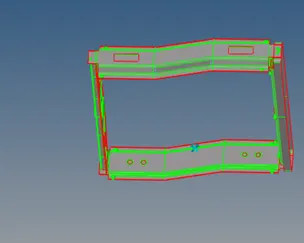
Figure1
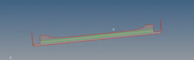
Figure 2
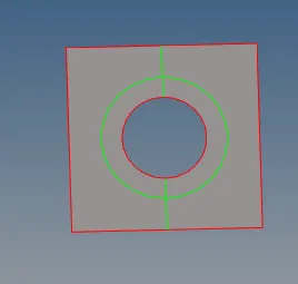
Figure3
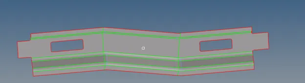
Figure4
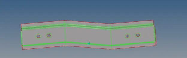
Figure 5
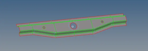
Figure 6
- The meshing strategy is to mesh surface by surface a while solving off elements and unnecessary tria elements
- After meshing the surface consider smoothing and/or element optimizing for better mesh flow
- It is a good idea to give nearby components different colours to help differentiate between parts while deploying connections.
- The final meshed component is shown below
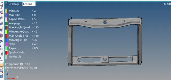
Figure7
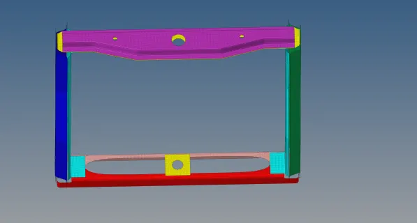
Figure 8
- After this we can start deploying connectors between different components.The different type of connections deployed will mostly consist of Hexa adhesive,seam welds,spot welds (along with rigid and spring type connections) and bolt welds.
- Enable the connector browser in the view->browser>hypermesh->connector.
- In the connectors option in 2d mesh panel we go to the bolt option.Select only the holes associated to the hole and the 2 components.
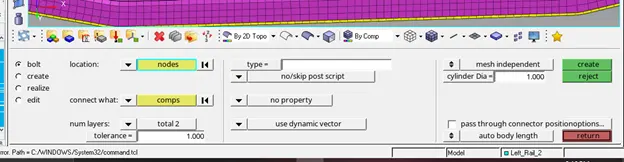
Figure9
- It is necessary to increase the maximum radius to 50 due to the large hole size.
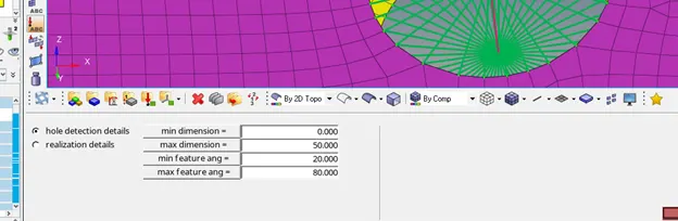
Figure 10
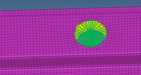
Figure 11
- Similarly for seam welds , select the node on any one component and set the weld angle as given.Select the components to join and create it.
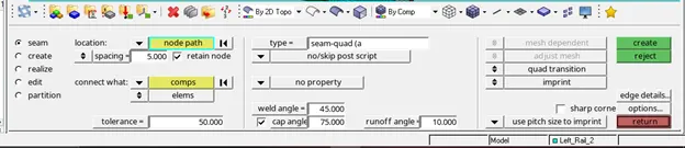
Figure 12
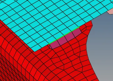
Figure 13
- It may be necessary to remesh the surface near the connectors to fix mesh quality,care should be taken to not select elements associated to the connection.
- Similarly for spot weld set the values as shown and select the nodes of any 1 layer.

Figure 14
- You may choose between 2 and 3 layer as needed.
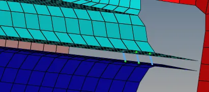
Figure 15
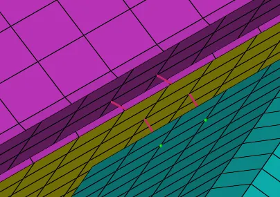
Figure 16
- Note:you can change the type of connection to rigid/spring type here in the options given.
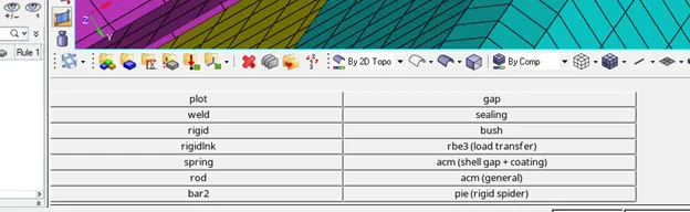
Figure 17
- For hexa adhesive type mesh, change the type in seam connector tab to hexa adhesive.Select the nodes appropriately and create the connection.
For multiple layer connections , layer 2 surfaces independent of the third and connect the common surface with the third as shown in figure 21.
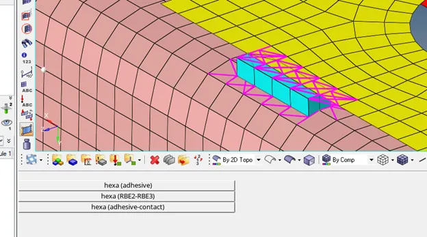
Figure 18
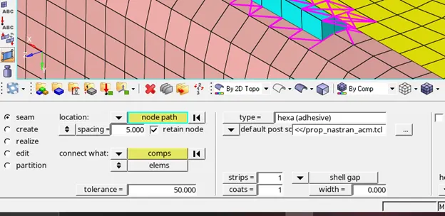
Figure 19
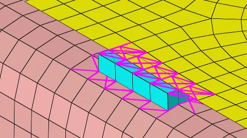
Figure 20
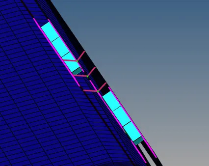
Figure 21
- Similarly deploy connections appropriately for the other portions of the model.
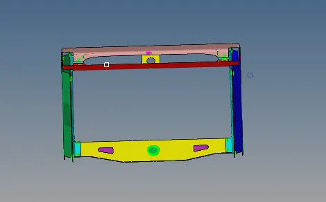
Figure 22
Learning Outcomes
- Connectors in hypermesh
- Remeshing after deploying connections
Conclusion
The model has been meshed according the given criteria successfully after which connections were deployed.