Week 9 - Creating connection for Rear door
AIM: The main aim of this challenge is to create different PID’s for the given rear door and provide necessary connections where ever it is required.
OBJECTIVE: The objectives of this challenge are as follows:
- To create different PID’s for the given rear door.
- To deploy suitable connections such as spot weld & bolt connections where ever it is required.
PROCEDURE:
- The CAD file in ANSA can be opened by selecting the open option in file tab.
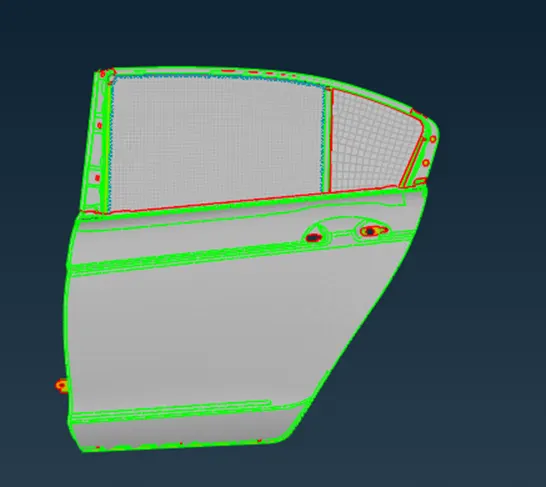
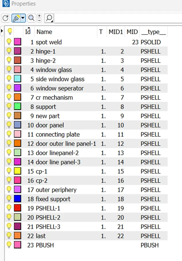
- Since the whole component is in one PID, and for deploying proper connections we need to create different PID’S (TOPO-->FACES-->SET PID) for all the sub parts present in the main component.
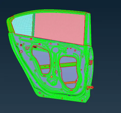
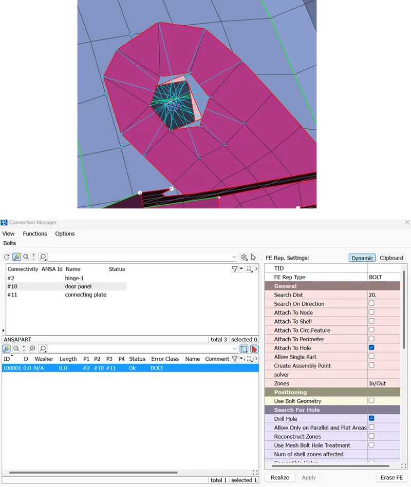
BOLT CONNECTION: For deploying a bolt connection first we need to create a 3D point. A 3D point has to be created on the COG of the circle where the bolt connection has to be deployed. The 3D point is then converted into bolt point using convert option in the assembly tab. After converting to bolt connection we must go to connection manager in the assembly tab for establishing the bolt connections. The parts which are to be connected by bolt has to be selected and in the FE representation tab bolt type connection is selected. The bolt connection is then realized after giving certain inputs such as search distance and zones.
RBE2 CONNECTIONS: These type of rigid body elements makes the connections rigid and prevents all translational and rotational DOF’S. This type of connections can be created between two or more components. A cluster RBE2 (NASTRAN-->ELEMENTS-->RBE2) connections can be deployed by selecting all the nodes (MANY NODES OPTION) on the perimeters (slave nodes) of the connecting parts at a time. A master node will be automatically created between the connecting parts and rigid connection will be established between the master and slave nodes.
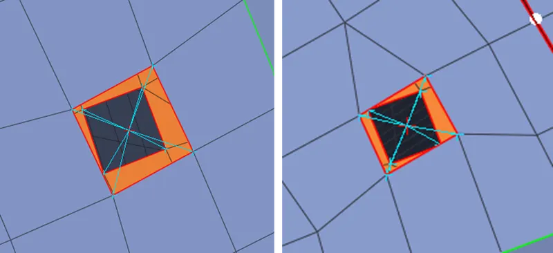
HINGE CONNECTIONS: For creating hinge connection, first we must deploy RBE2 cluster connections on both the sides of the hinges. Now by using RBE2 two nodes method a rotating link can be created between the two sides of hinges by releasing the DOF in rotational Z- direction.
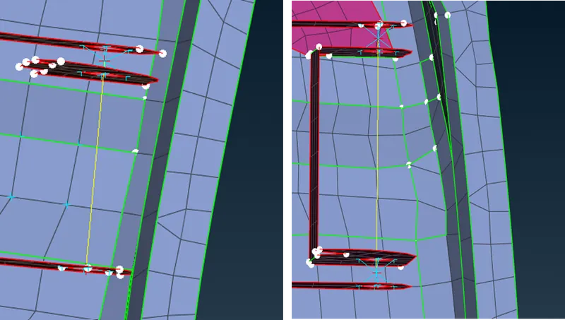
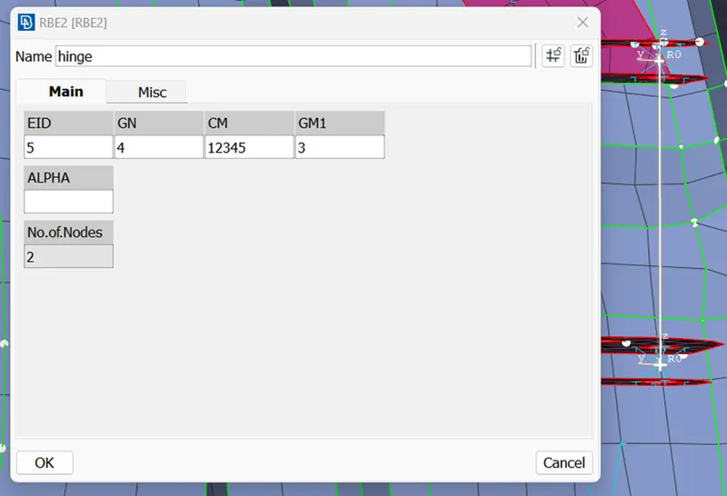
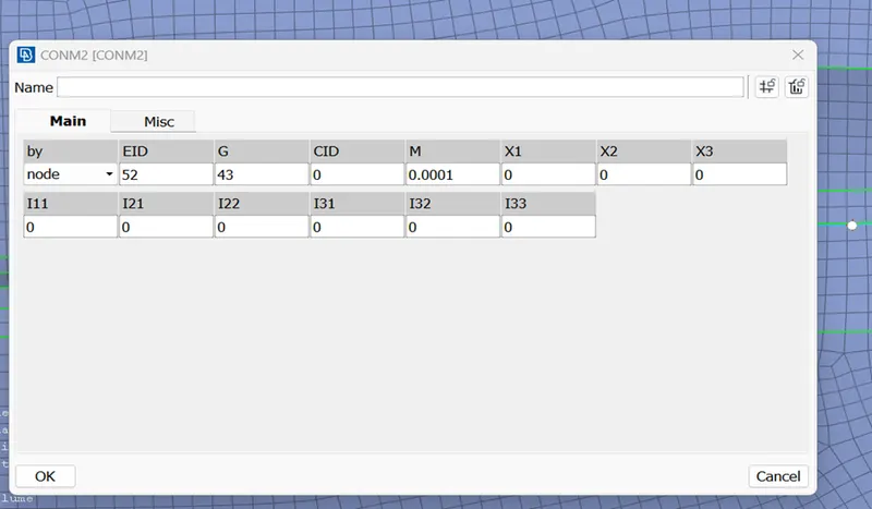
CONCENTRATED MASS CONNECTIONS: A concentrated mass has to be deployed on the door handle for representing mechanism. Initially a cluster RBE2 connections must be deployed on two sides of door handle. Now one more RBE2 connection has to be deployed between the two master nodes of the initially formed RBE2 connections, now a concentrated mass (NASTRAN-->ELEMENTS-->CONMi-->CONM2-->NODES) of 0.0001 tonnes has to be deployed on the finally formed master node.
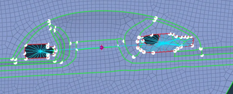
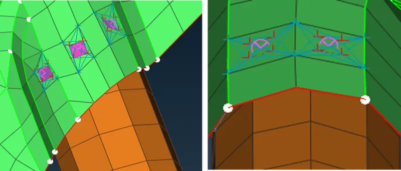
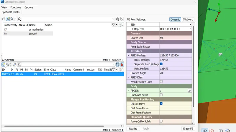
SPOT WELD CONNECTIONS: For creating a spot weld connection between the parts, we need to create a 3D point on one of the surfaces that needs to be joined. That 3D point is now converted to spot weld point using convert option in assembly tab. After converting to spot weld point, we must go to connection manager in the assembly tab for establishing the spot weld connections. The parts which are to be connected by spot weld has to be selected and in the FE representation tab RBE3-HEXA-RBE3 type connection is selected. The spot weld connection is then realized after giving certain inputs such as search distance and RBE3 pin flags
.
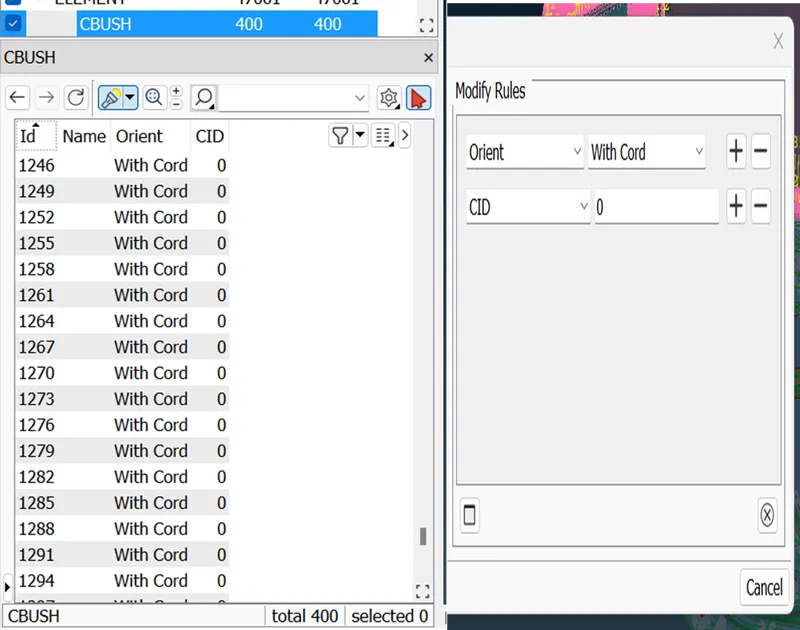
RBE3-CBUSH-RBE3 CONNECTIONS: These are weather strip connections used to establish a connection between glass window and door panel. Initially a curve (MESH-->PERIMETERS-->FEAT2CURVE) is extracted from the edges of the glass door. Then the curve is converted to spot line using convert option in assembly tab. After converting to spot weld line, we must go to connection manager in the assembly tab for establishing the CBUSH connections. The parts which are to be connected by CBUSH has to be selected and in the FE representation tab RBE3-CBUSH-RBE3 type connection is selected. The CBUSH connection is then realized after giving certain inputs such as search distance and selecting keep all branches.
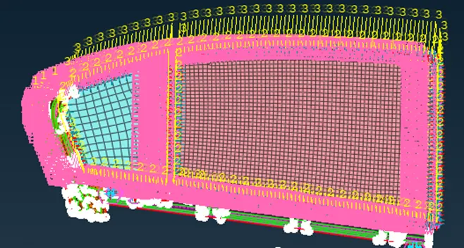
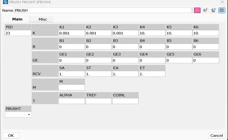
We must make sure local coordinates should be aligning with the global coordinates. If not, then we must change the orientation of the element from local to global coordinate system.
Learning outcomes:
- Learnt about Creating different PID’S for different parts.
- Learnt about assigning mass to the body.
- Learnt about deploying different types of connections such as spot weld, seam weld and bolt type connections.
conclusion: So for the given model different PID’S have been created and necessary connections have been deployed where ever it was required.