Project 1 - Meshing of Floor Panel
AIM: The main aim of this challenge is to mesh the given floor panel as per below element quality criteria.
|
S.no |
Element Quality Criteria |
Value |
|
1 |
Target/Average length |
5 |
|
2 |
Minimum Length |
2 |
|
3 |
Maximum Length |
8 |
|
4 |
Aspect |
5 |
|
5 |
Warpage |
15 |
|
6 |
Skewness |
45 |
|
7 |
Taper |
0.5 |
|
8 |
Minimum Quad Angle |
45 |
|
9 |
Maximum Quad Angle |
135 |
|
10 |
Minimum Tria Angle |
20 |
|
11 |
Maximum Tria Angle |
120 |
|
12 |
Tria Percentage |
10 |
OBJECTIVE: The objectives of this challenge are as follows:
- To perform geometry clean up and generating mid surface for the given component.
- To mesh the given component with less tria concentration and good mesh flow.
- Finally all the elements should pass for given element quality criteria.
PROCEDURE:
- The CAD file in ANSA can be opened by selecting the open option in file tab.
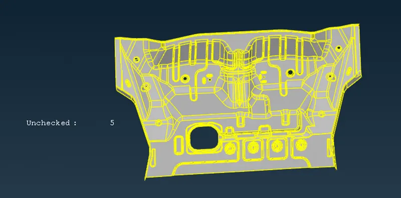
- After opening the file, topo operation (TOPO MODULE-->FACES-->TOPO) was performed to convert the unstitched surfaces (single cons) to stitched surfaces (double cons).
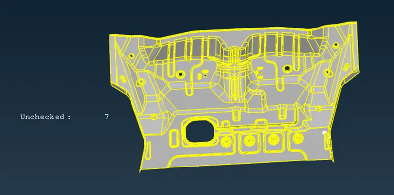
- After performing the topo operation, geometry check (TOOLS-->CHECK--> GEOMETRY) was done in order to remove geometrical errors.
- Geometry check was done for unchecked faces, collapsed cons, triple cons, needle faces, overlap faces, cracks & single cons.
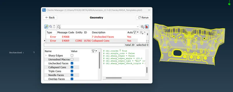
- Some of the errors can be fixed automatically by using fix option and the errors that cannot be fixed automatically needs human attention and those errors should be solved manually.
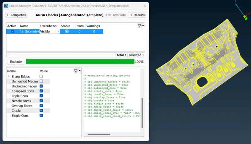
- Once all the errors are rectified, we are good to go for extracting mid surface of the given component.
- Mid surface can be extracted by using mid surface (skin method) method (TOPO MODULE --> FACES--> MID SURFAC-->SKIN).
- Mid surface is automatically extracted exactly at an offset distance of half of the thickness of that particular parent geometry.
- In the skin method, the thickness for the component will be automatically assigned to particular component once the mid surface is generated.

- After mid surface generation, again geometry check has been done and all the errors in mid surface were fixed.
- Before meshing the component, all the macros and perimeters of the given assembly were set to target length using length option in perimeters tab of mesh module. (MESH MODULE--> PERIMETERS--> LENGTH). Element Quality criteria was also set according to the given question.
- After setting the target length whole component was checked for geometry and at critical places defeaturing was done where ever it was required.
- After the geometry check, we must go to batch mesh module and the obtained mid surface PID has been added to meshing scenario.
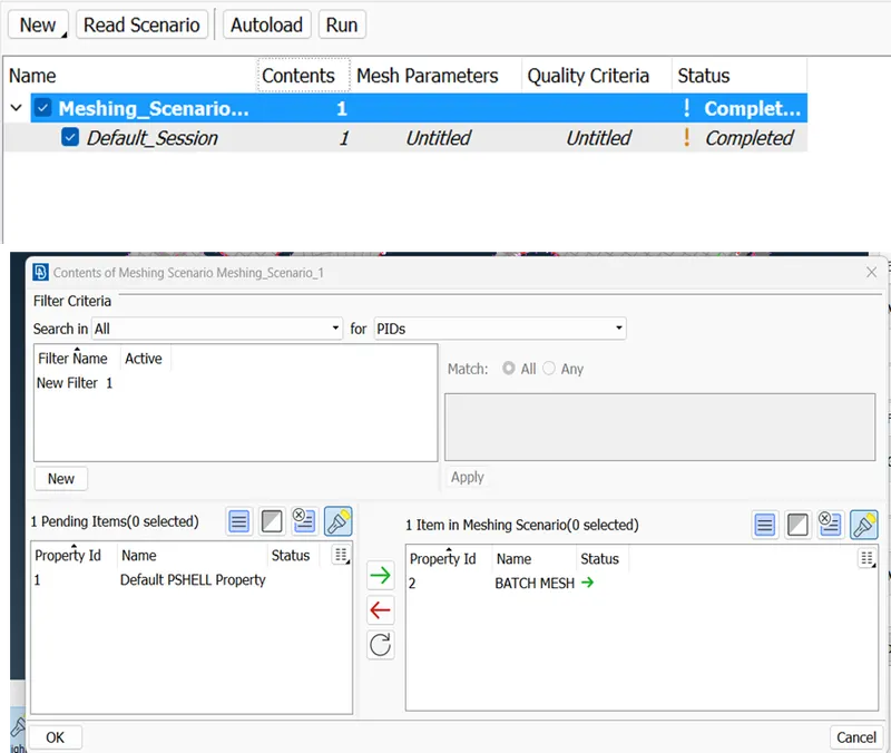
- After adding the PID to meshing scenario, the whole component was automatically meshed by considering the quality criteria.
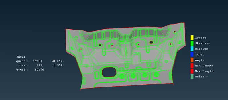
- For obtaining good mesh flow several commands like swap, split, paste, collapse& join commands were used.
CONCLUSIONS:
- Learnt about geometry clean up and extracting the mid surface using skin mid surface options.
- Learnt about how to mesh a component for a given quality element criteria using batch mesh module.
RESULTS:
Geometry cleanup, mid surface extraction and meshing of the given component was done successfully. Trias concentration was limited to less than 2.0%.