Week - 5 - 2D meshing for Plastic components
AIM: The main aim of this challenge is to mesh the given bottle cap model as per below element quality criteria.
|
S.no |
Element Quality Criteria |
Value |
|
1 |
Target/Average length |
1 |
|
2 |
Minimum Length |
0.5 |
|
3 |
Maximum Length |
3 |
|
4 |
Aspect |
3 |
|
5 |
Warpage |
15 |
|
6 |
Skewness |
45 |
|
7 |
Jacobian |
0.7 |
|
8 |
Minimum Quad Angle |
45 |
|
9 |
Maximum Quad Angle |
135 |
|
10 |
Minimum Tria Angle |
30 |
|
11 |
Maximum Tria Angle |
120 |
|
12 |
Tria Percentage |
15 |
OBJECTIVE: The objectives of this challenge are as follows:
- To perform geometry clean up and generating mid surface for the given component.
- To mesh the given component with less tria concentration and good mesh flow.
- Finally all the elements should pass for given element quality criteria.
PROCEDURE:
- The CAD file in ANSA can be opened by selecting the open option in file tab.
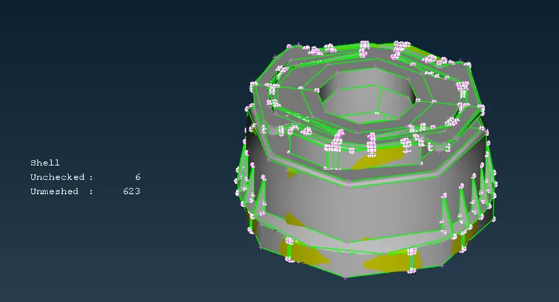
- After opening the file, topo operation (TOPO MODULE-->FACES-->TOPO) was performed to convert the unstitched surfaces (single cons) to stitched surfaces (double cons).
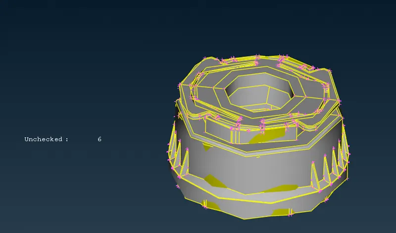
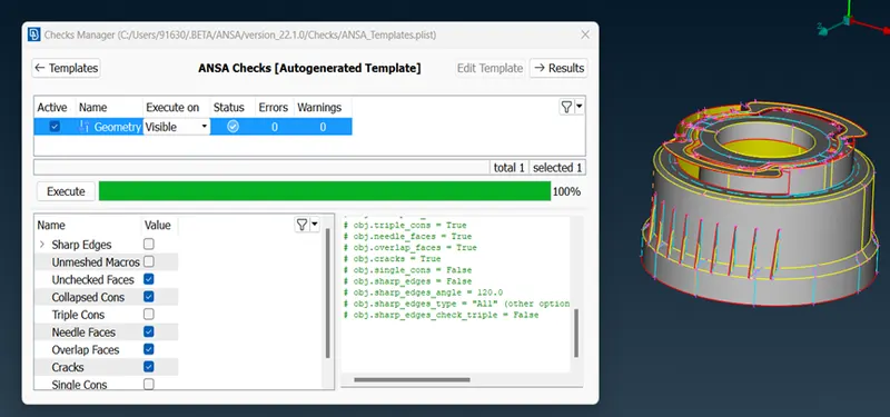
- After performing the topo operation, geometry check (TOOLS-->CHECK--> GEOMETRY) was done in order to remove geometrical errors.
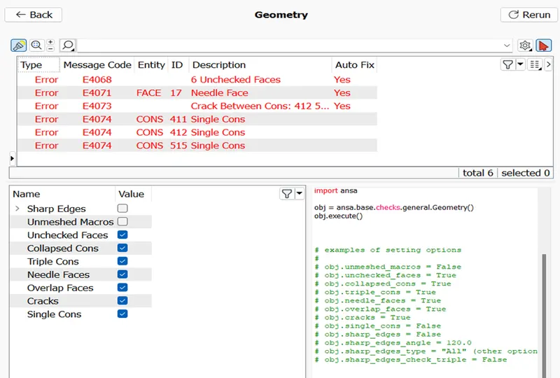
- Geometry check was done for unchecked faces, collapsed cons, triple cons, needle faces, overlap faces, cracks & single cons.
- Some of the errors can be fixed automatically by using fix option and the errors that cannot be fixed automatically needs human attention and those errors should be solved manually.
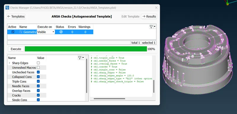
- Once all the errors are rectified, we are good to go for extracting mid surface of the given component.
- Mid surface can be extracted by using FACES OFFSET & MIDDLE method (TOPO MODULE --> FACES--> OFFSET-->FACES) &( TOPO MODULE --> FACES--> MIDDLE-->SINGLE) .
- Mid surface is automatically extracted exactly at an offset distance of half of the thickness of that parent geometry. Several other options like extend, cons to curve, curves middle, faces new were also used to extract the mid surface.
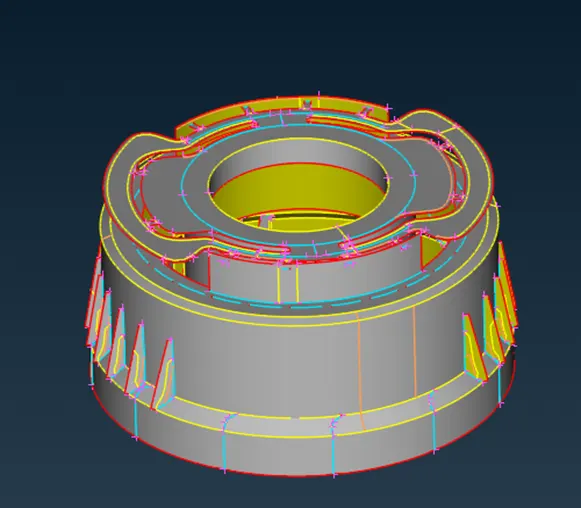
- After mid surface generation, again geometry check has been done and all the errors in mid surface were fixed.
- Before meshing the component, all the macros and perimeters of the given assembly were set to target length using length option in perimeters tab of mesh module. (MESH MODULE--> PERIMETERS--> LENGTH). Element Quality criteria was also set according to the given question.
- After setting the target length whole component was checked for geometry and at critical places defeaturing was done where ever it was required.
- After the geometry check, we must go to batch mesh module and the obtained mid surface PID has been added to meshing scenario.
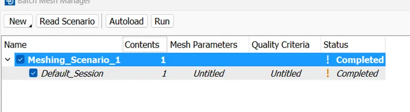
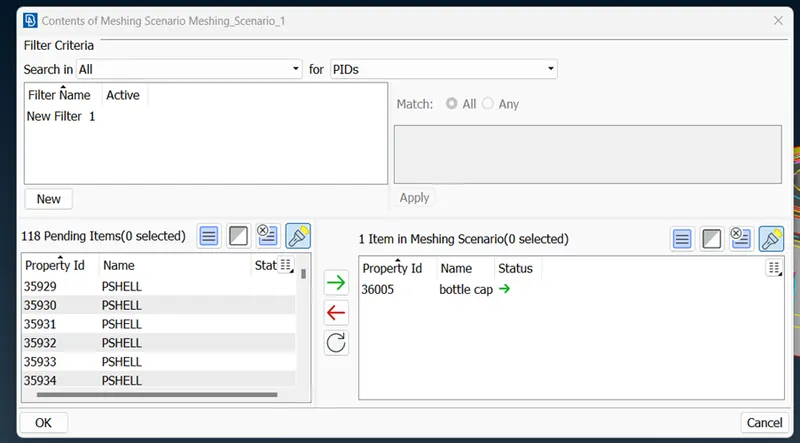
- After adding the PID to meshing scenario, the whole component was automatically meshed by considering the quality criteria.
- For obtaining good mesh flow several options like swap, split, paste, collapse& join commands were used.
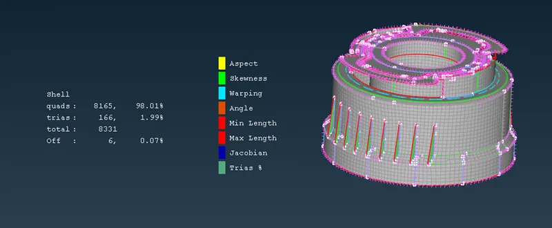
- After meshing each feature thickness was checked manually and separate PID’S were assigned to different thickness features.
NOTE: The element failures near triple cons were left alone like that.
CONCLUSIONS:
- Learnt about geometry clean up and extracting the mid surface using offset& middle options.
- Learnt about how to mesh a component for a given quality element criteria using batch mesh module.
RESULTS:
Geometry cleanup, mid surface extraction and meshing of the given component was done successfully. Trias concentration was limited to less than 2.0%.