Project 2
Objective : To mesh the given component according to given quality criteria and assign thickness.
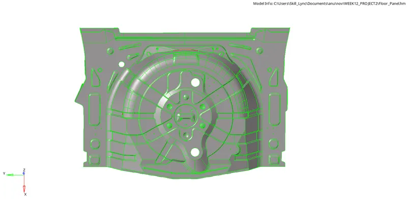
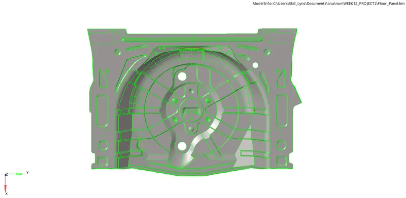
Procedure : The given model was imported and visually inspected for surface deformations.
The geometry colour mode was set to By Topo for identification of free edges .
Step 1 : Geometry Clean up
The free edges on the surfaces were cleared using toggle edge and replace point from quick edit of geometry module .
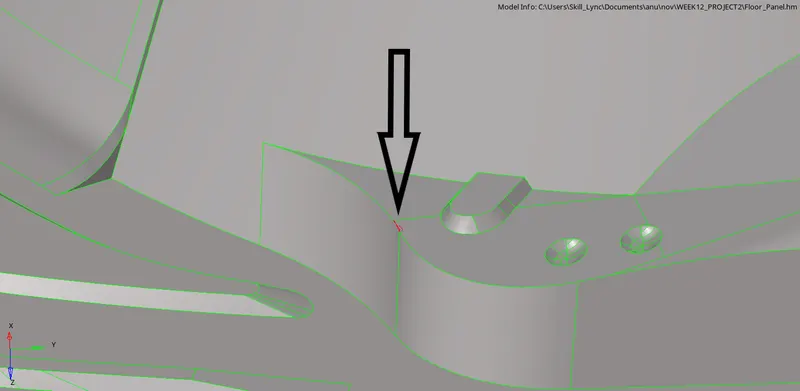
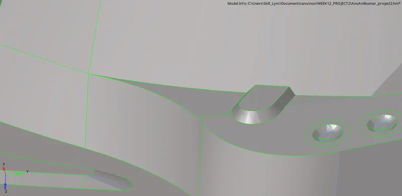


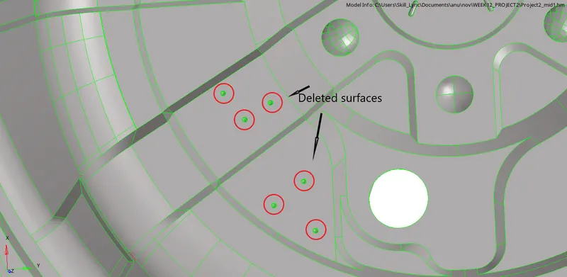
Additional surfaces were deleted and new surfaces were created using ruled option from surfaces .
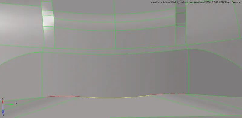
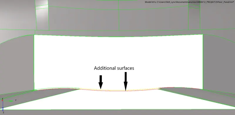
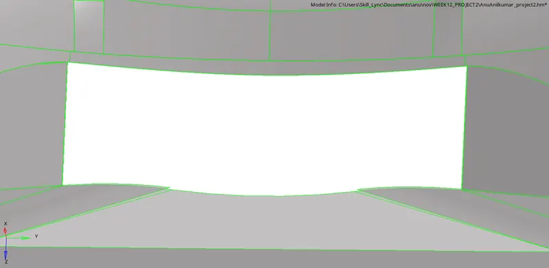

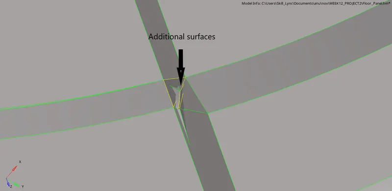
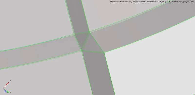
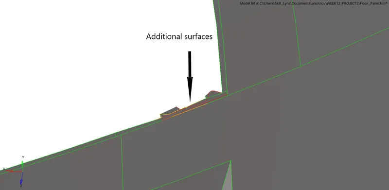
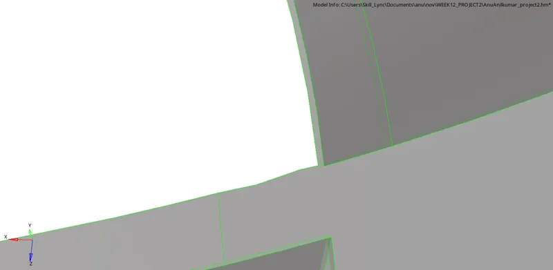
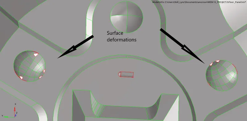
Points on surface edges with deformations were release using release point option from quick edit . Those surface edges were then toggled using toggle edge option .
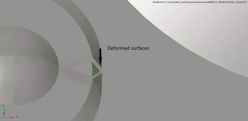
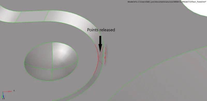
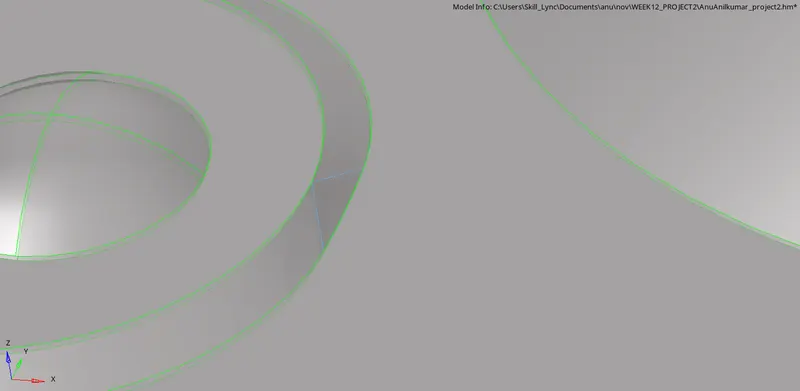

Hence the geometry clean up was completed on the component .
Step 2 : Midsurface
Midsurface for the component was obtained using automidsurface tool with extractions option as offsets+planes+sweeps .
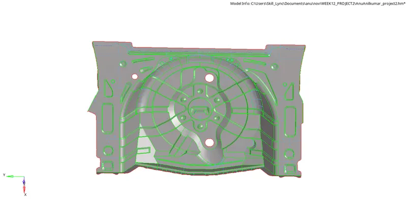


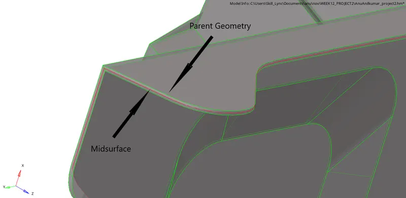
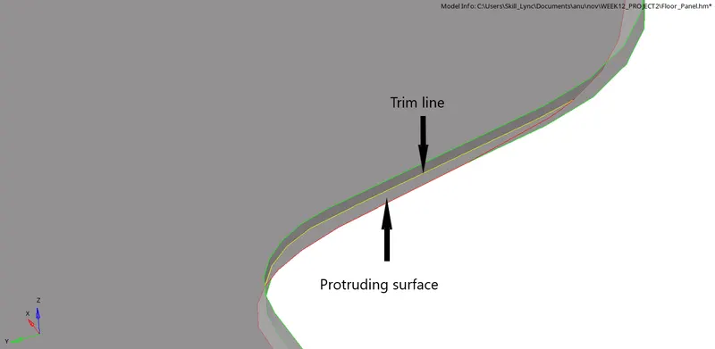
The surface which were protruding out from parent geometry was trimmed and deleted using trim sith surfaces option from surface edit panel of geometry module .
Surfaces with size much less than minimum length were deleted using using delete option and those surfaces were filled using filler surface option from quick edit .


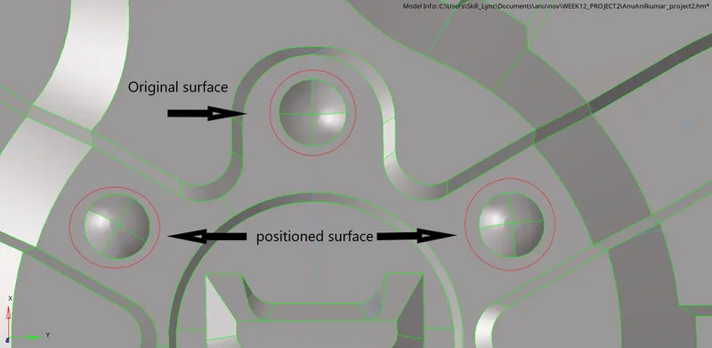
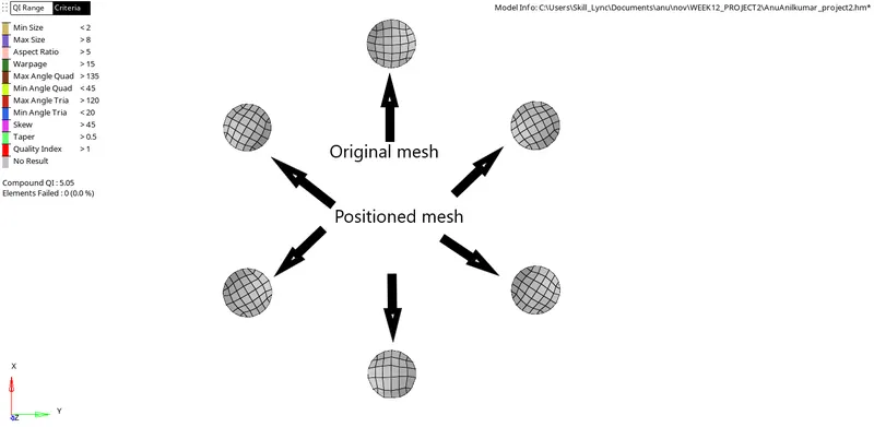
Deformations in the concave and convex surfaces were cleared by deleting those surfaces and using position tool to postion those surfaces again from a surface without deformations . The position tool was applied by selecting and duplicating the surfaces to be positioned and selecting the from and to vector points about which it has to be positioned .

Hence the midsurface for the component was created .
Step 3 : Meshing
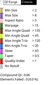
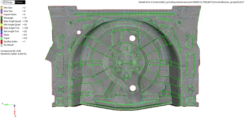
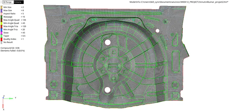
To Mesh the component as per given quality criteria , the given values were entered using crtiteria file settings option from preferences panel .
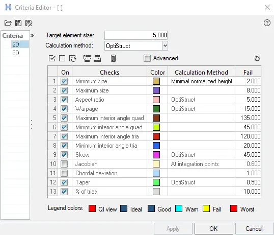
To mesh the given components , the surfaces were selected part by part and meshed by keeping the target element length as 5 from automesh option of 2d module .
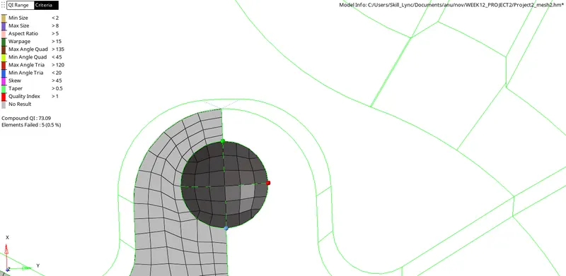

Elements on the concave and convex surfaces were positioned after meshing a single concave surface using position tool as mentioned earlier . The only difference being that , instead of surfaces, elements were selected and duplicated .

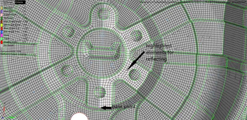
Elements on symmetrical surfaces were duplicated and reflected by using reflect tool from tools panel . The highlighted elements were selected and reflected after selecting reflect about y axis and marking base point .
Tria elements were arranged and opposite trias were dragged and cancelled .
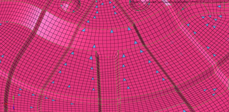
Elements failing for minimum thickness were rectified using distance option from geometry module . Elements failing for Minimum and maximum angle quad were rectified using the same .
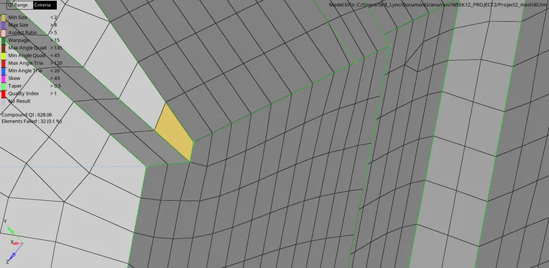
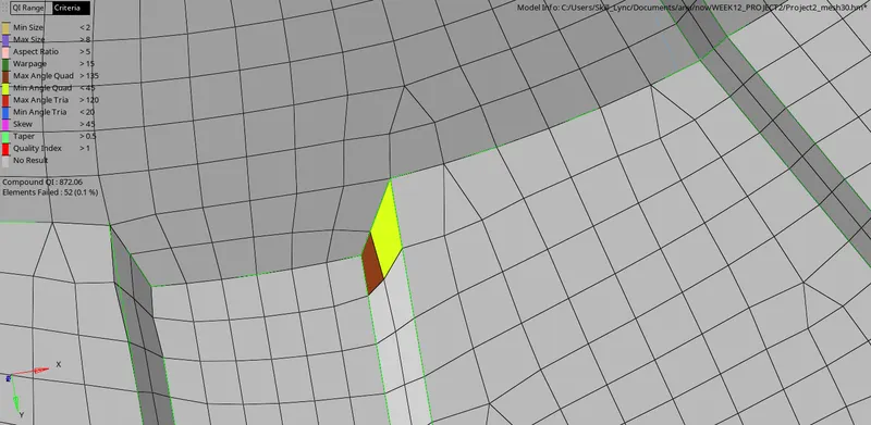
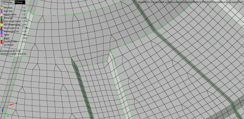
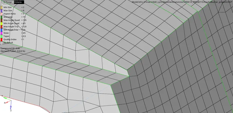

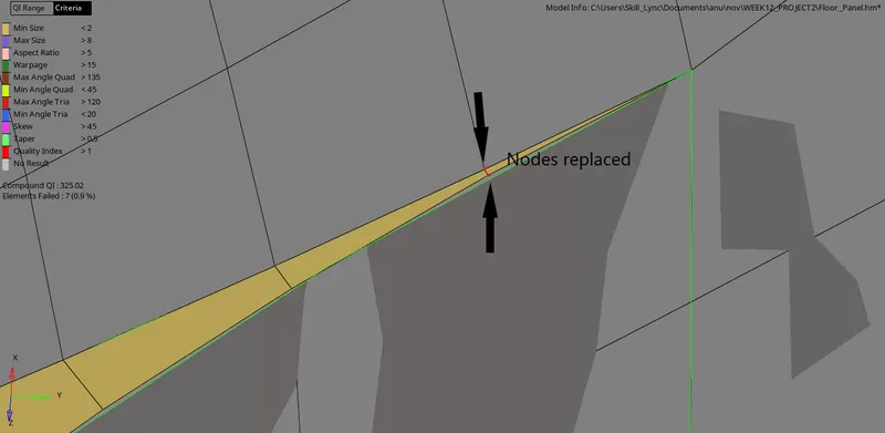
Tria elements failing for very low length were rectified by replacing the nodes using node edit function from 2D module .
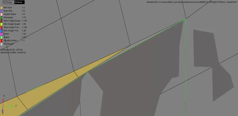

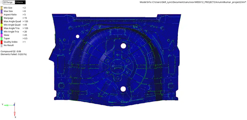
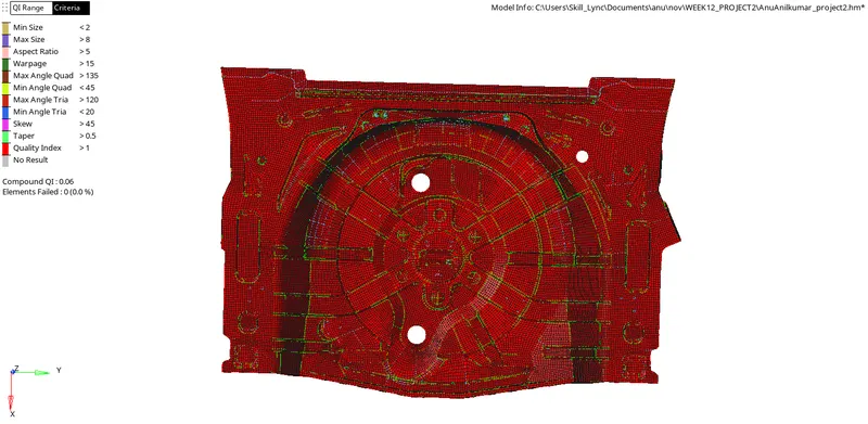
Hence the component was meshed as per given qyality criteia with zero elements failing .
Step 4 : Assigning Thickness
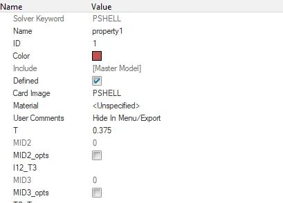
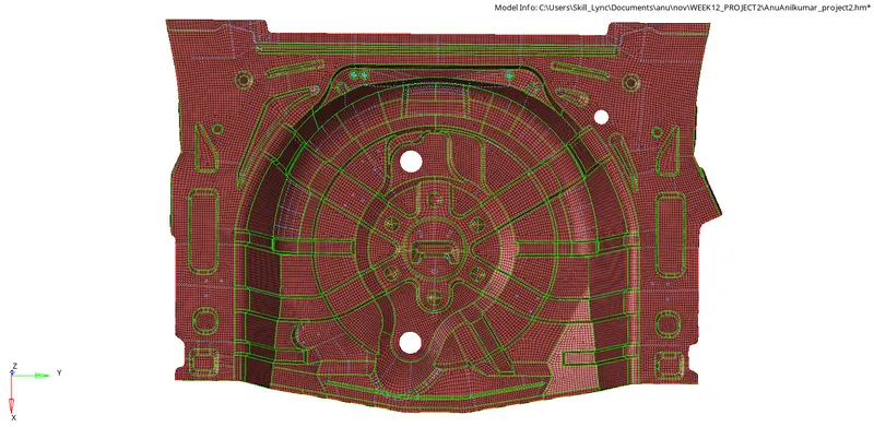
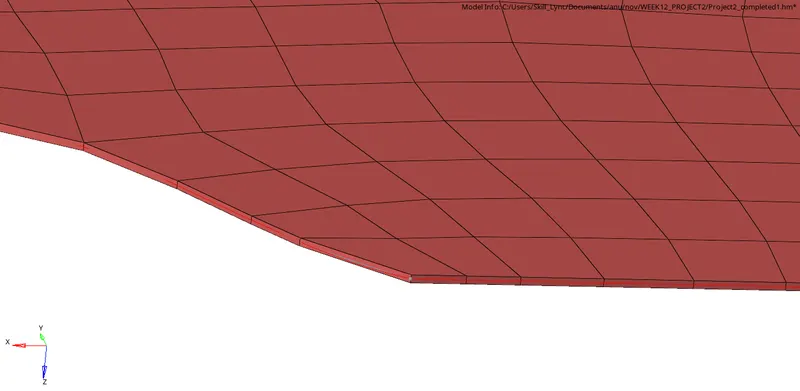
To assign thickness to elements , since there is only a single thickness for the entire component , a property was created and thickness of 0.375 was assigned to it .The property was assigned to the component using assign function . The element represenation was changed from traditional to detailed 2D element representation to view the assigned thickness.
Step 5: Checking normal
To check the element normal , the normal panel from tools module was selected , the displayed 2D elements were chosen and normal was checked . Adjust option was used to correct normals which were in reverse direction .
Result :
1) Geometry clean up was performed on the given component so as to remove any unwanted free edges and surface deformations.
2) Midsurface of the component was extracted .
3) The component was meshed according to given element quality criteria with zero elements failure .
4) Thickness was assigned to the component .