Deploying connectors on the given component as per given connection details.
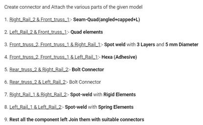
Objective: Deploying connectors on the given component as per given connection details as shown below.
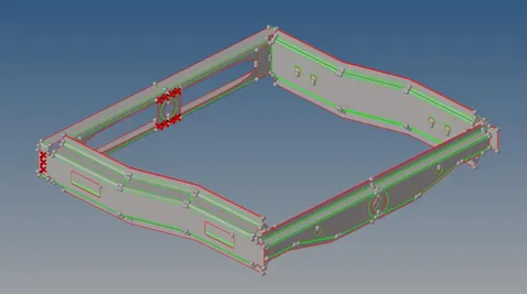
CAD model images:
Procedure:
- The given model is a frame assembly welding model which consists of various components such as Front truss 1, Front truss 2, Reinf plate, Right Rail 1, Right Rail 2, Left Rail 1, Left Rail 2, Rear truss 1, Rear truss 2.
- The process that needs to be done on the given components is as follows:
- Mesh the given components and give them different colours to distinguish them visually.
- Attach various components of the model by connecting them with mentioned connector details.
1. Right Rail 2 & Front truss 1
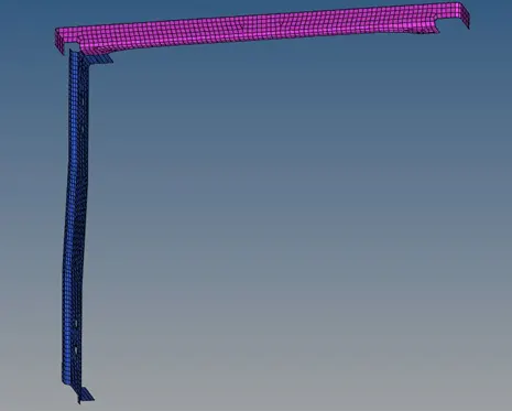
- Turn on the “Right Rail 2 & Front truss 1” components and turn off all other components.
- Connectors can only be deployed on meshed components, so the components must be meshed first.
- To mesh the components, go to 2D options menu and click on “automesh” tab. Now select the surface of the components and by giving proper element size & mesh type click on mesh option.
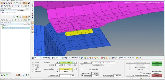
- Now, between the meshed components a connector type named “Seam Quad(angled+capped +L)” has to be created.
- So, to do that go to “connectors” tab in the 2D options menu. Now in the connectors tab select “seam” option.
- In the “location” option choose nodelist and select nodes by path on the mesh components at the area where they are near and can be connected.
- In the “connect what” option choose the components between which the connector has to be created.
- In the “type” option select “seam quad(angled+capped +L)” and give appropriate spacing, tolerance ,weld angle, cap angle, run off angle values and click on create.
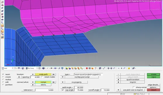
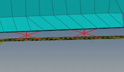
- The connector is now created and can be seen with proper representation. If the connector is realized then it can be seen as green wire or else it will be red wire, in such case it needs to be modified and rerealized again.
- The properties of the connectors can be viewed in the connectors section which is enabled in the “view” section of the menu bar.
2. Left Rail 2 & Front truss 1
- Turn on the “Left Rail 2 & Front truss 1” components and turn off all other components.
- Connectors can only be deployed on meshed components, so the components must be meshed first.
- To mesh the components, go to 2D options menu and click on “automesh” tab. Now select the surface of the components and by giving proper element size & mesh type click on mesh option.
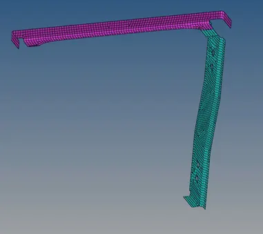
- Now, between the meshed components a connector type named “Quad elements” has to be created.
- So, to do that go to “connectors” tab in the 2D options menu. Now in the connectors tab select “seam” option.
- In the “location” option choose nodelist and select nodes by path on the mesh components at the area where they are near and can be connected.
- In the “connect what” option choose the components between which the connector has to be created.
- In the “type” option select “quads” and give appropriate spacing, tolerance values and click on create.
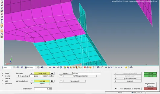
- The connector is now created and can be seen with proper representation. If the connector is realized then it can be seen as green wire or else it will be red wire, in such case it needs to be modified and rerealized again.
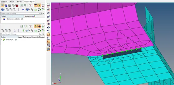
- The properties of the connectors can be viewed in the connectors section which is enabled in the “view” section of the menu bar.
3. Front truss 2, Front truss 1 & Right Rail 1
- Turn on the “Front truss 2, Front truss 1 & Right Rail 1” components and turn off all other components.
- Connectors can only be deployed on meshed components, so the components must be meshed first.
- To mesh the components, go to 2D options menu and click on “automesh” tab. Now select the surface of the components and by giving proper element size & mesh type click on mesh option.
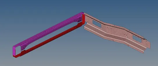
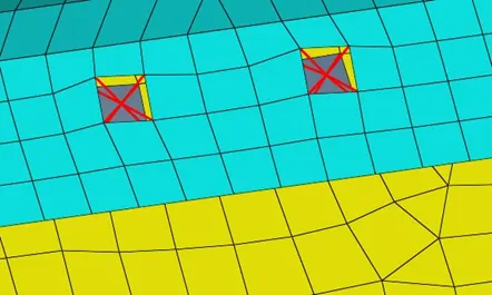
- Now, between the meshed components a connector type named “Spot weld” with 3 layers & 5mm diameter has to be created.
- So, to do that go to “connectors” tab in the 2D options menu. Now in the connectors tab select “spot” option.
- In the “location” option choose nodelist and select nodes by path on the mesh components at the area where they are near and can be connected.
- In the “connect what” option choose the components between which the connector has to be created.
- In the “type” option select “weld” and give proper tolerance value and set the number of layers as 3 & diameter as 5mm and click on create.
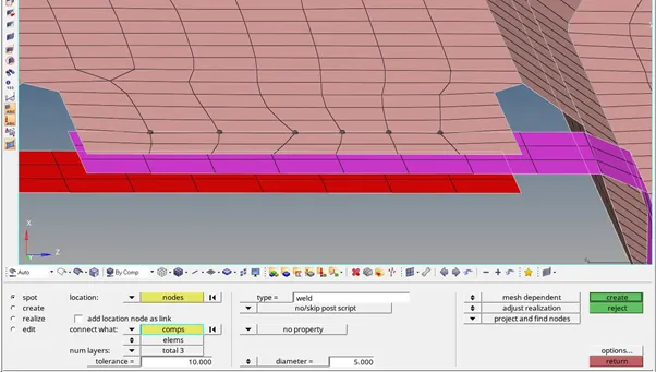
- The connector is now created and can be seen with proper representation. If the connector is realized then it can be seen as green wire or else it will be red wire, in such case it needs to be modified and rerealized again.
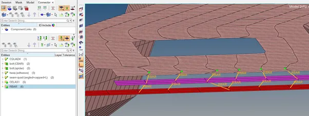
- The properties of the connectors can be viewed in the connectors section which is enabled in the “view” section of the menu bar.
4. Front truss 2, Front truss 1 & Left Rail 1
- Turn on the “Front truss 2, Front truss 1 & Left Rail 1” components and turn off all other components.
- Connectors can only be deployed on meshed components, so the components must be meshed first.
- To mesh the components, go to 2D options menu and click on “automesh” tab. Now select the surface of the components and by giving proper element size & mesh type click on mesh option.
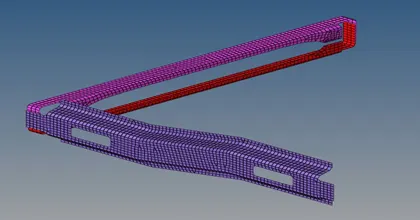
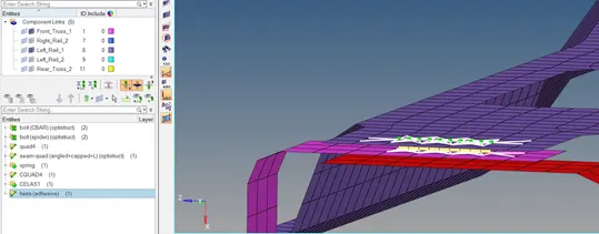
- Now, between the meshed components a connector type named “Hexa(adhesive)” has to be created.
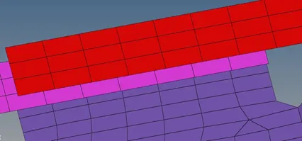
- So, to do that go to “connectors” tab in the 2D options menu. Now in the connectors tab select “seam” option.
- In the “location” option choose nodelist and select nodes by path on the mesh components at the area where they are near and can be connected.
- In the “connect what” option choose the components between which the connector has to be created.
- In the “type” option select “Hexa(adhesive)” and give appropriate spacing, tolerance values and click on create.
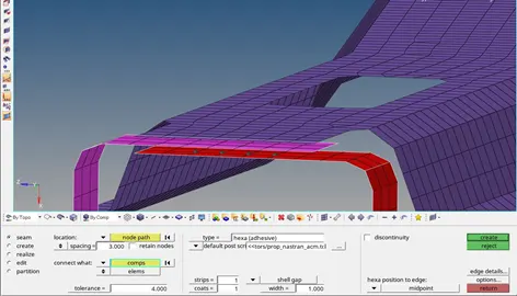
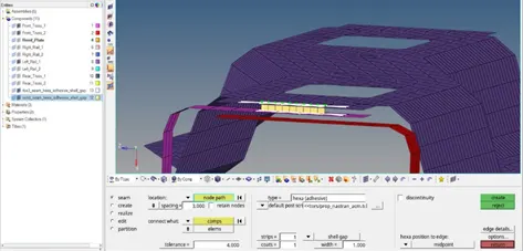
Connector created between 1st two components
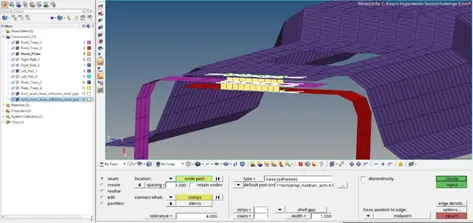
Connector created between next two components
- The connector is now created and can be seen with proper representation. If the connector is realized then it can be seen as green wire or else it will be red wire, in such case it needs to be modified and rerealized again.
- The properties of the connectors can be viewed in the connectors section which is enabled in the “view” section of the menu bar.
5. Rear truss 2 & Right Rail 2
- Turn on the “Rear truss 2 & Right Rail 2” components and turn off all other components.
- Connectors can only be deployed on meshed components, so the components must be meshed first.
- To mesh the components, go to 2D options menu and click on “automesh” tab. Now select the surface of the components and by giving proper element size & mesh type click on mesh option.
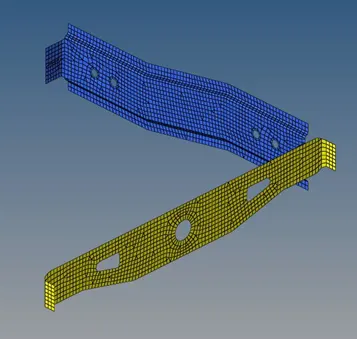
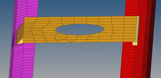
- Now, between the meshed components a connector type named “Bolt connector” has to be created.
- So, to do that go to “connectors” tab in the 2D options menu. Now in the connectors tab select “bolt” option.
- In the “location” option choose nodelist and select nodes by path on the mesh components at the area where they are near and can be connected.
- In the “connect what” option choose the components between which the connector has to be created.
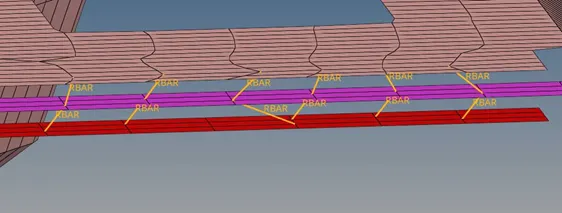
- In the “type” option select “bolt(CBAR)” which is chosen here and give proper tolerance value and in the third section select “create hole, if none” option & click on create.
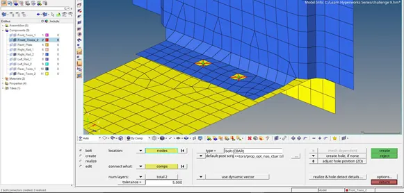
- The connector is now created and can be seen with proper representation. If the connector is realized then it can be seen as green spots or else it will be red spots, in such case it needs to be modified and rerealized again.
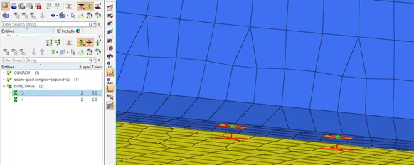
- The properties of the connectors can be viewed in the connectors section which is enabled in the “view” section of the menu bar.
6. Rear truss 2 & Left Rail 2
- Turn on the “Rear truss 2 & Left Rail 2” components and turn off all other components.
- Connectors can only be deployed on meshed components, so the components must be meshed first.
- To mesh the components, go to 2D options menu and click on “automesh” tab. Now select the surface of the components and by giving proper element size & mesh type click on mesh option.
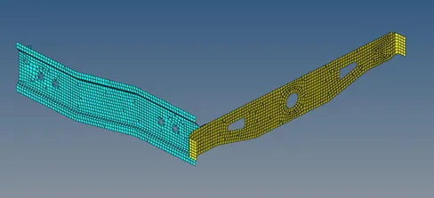
- Now, between the meshed components a connector type named “Bolt connector” has to be created.
- So, to do that go to “connectors” tab in the 2D options menu. Now in the connectors tab select “bolt” option.
- In the “location” option choose nodelist and select nodes by path on the mesh components at the area where they are near and can be connected.
- In the “connect what” option choose the components between which the connector has to be created.
- In the “type” option select “bolt(spider)” which is chosen in this case and give proper tolerance value and in the third section select “create hole, if none” option & click on create.
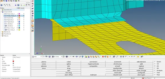
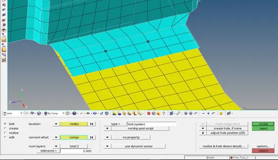
- The connector is now created and can be seen with proper representation. If the connector is realized then it can be seen as green spots or else it will be red spots, in such case it needs to be modified and rerealized again.
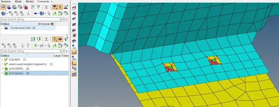
- The properties of the connectors can be viewed in the connectors section which is enabled in the “view” section of the menu bar.
- Right Rail 1 & Right Rail 2
- Turn on the “Right Rail 1 & Right Rail 2” components and turn off all other components.
- Connectors can only be deployed on meshed components, so the components must be meshed first.
- To mesh the components, go to 2D options menu and click on “automesh” tab. Now select the surface of the components and by giving proper element size & mesh type click on mesh option.
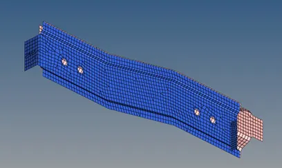
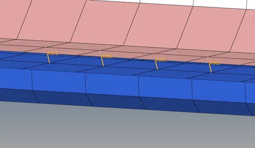
- Now, between the meshed components a connector type named “Spot-weld” with rigid elements has to be created.
- So, to do that go to “connectors” tab in the 1D options menu. Now in the spotweld tab select “using nodes” option and place nodes on the meshed components.
- In the “element config” option choose “rigid” and click on middle mouse button.
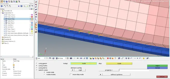
- The connector is now created and can be seen with proper representation. If the connector is realized then it can be seen as green wire or else it will be red wire, in such case it needs to be modified and rerealized again.
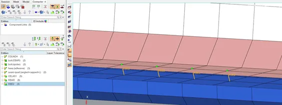
- The properties of the connectors can be viewed in the connectors section which is enabled in the “view” section of the menu bar.
- Left Rail 1 & Left Rail 2
- Turn on the “Left Rail 1 & Left Rail 2” components and turn off all other components.
- Connectors can only be deployed on meshed components, so the components must be meshed first.
- To mesh the components, go to 2D options menu and click on “automesh” tab. Now select the surface of the components and by giving proper element size & mesh type click on mesh option.
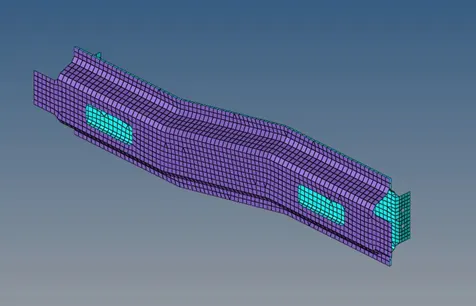
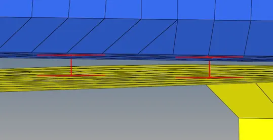
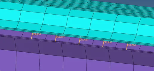
- Now, between the meshed components a connector type named “Spot-weld” with spring elements has to be created.
- So, to do that go to “connectors” tab in the 1D options menu. Now in the spotweld tab select “using nodes” option and place nodes on the meshed components.
- In the “element config” option choose “spring” and click on middle mouse button.
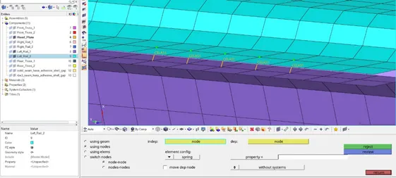
- The properties of the connectors can be viewed in the connectors section which is enabled in the “view” section of the menu bar.
- Rest of the components
- At this stage only “Reinf plate” is left to be connected, so turn on the “Front truss 1, Front truss 2 & Reinf plate” components and turn off all other components.
- Connectors can only be deployed on meshed components, so the plate component must be meshed first.
- To mesh the component, go to 2D options menu and click on “automesh” tab. Now select the surface of the component and by giving proper element size & mesh type click on mesh option.
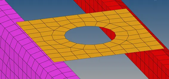
- Now, there are two sides of the plate between which connectors has to be created.
- So, at one side different connector is created. To do that go to “connectors” tab in the 2D options menu. Now in the connectors tab select “seam” option.
- In the “location” option choose nodelist and select nodes by path on the meshed components at the area where they are near and can be connected.
- In the “connect what” option choose the components between which the connector has to be created.
- In the “type” option select “seam quad(angled+capped +L)” which is chosen in this case and give appropriate spacing, tolerance ,weld angle, cap angle & run off angle values & click on create.
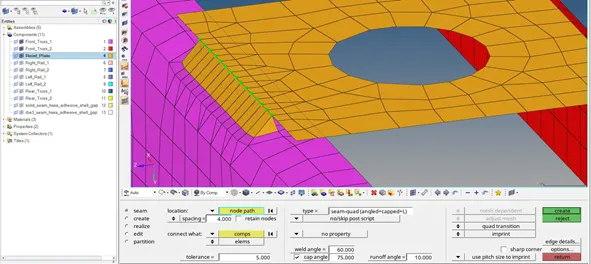
- The connector is now created and can be seen with proper representation. If the connector is realized then it can be seen as green wire or else it will be red wire, in such case it needs to be modified and rerealized again.
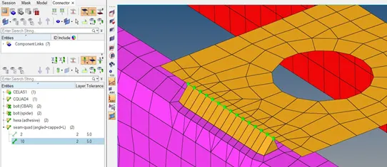
- At the other side another connector is created. To do that go to “connectors” tab in the 2D options menu. Now in the connectors tab select “seam” option.
- In the “location” option choose nodelist and select nodes by path on the meshed components at the area where they are near and can be connected.
- In the “connect what” option choose the components between which the connector has to be created.
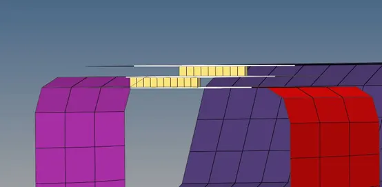
- In the “type” option select “Hexa(adhesive)” which is chosen in this case and give appropriate spacing, tolerance values and width as 4mm & click on create.
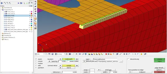
- The connector is now created and can be seen with proper representation. If the connector is realized then it can be seen as green wire or else it will be red wire, in such case it needs to be modified and rerealized again.
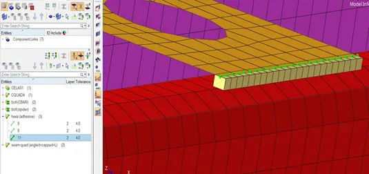
- The properties of the connectors can be viewed in the connectors section which is enabled in the “view” section of the menu bar.
Results:
Final model images
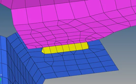
1
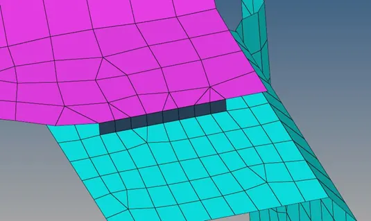
2
3
4
5
6
6
7
8
9