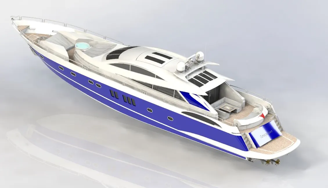
Design, Modelling and Assembly of a Sunseeker Predator Yacht.
Introduction: All parts of the Yacht were modelled individually and assembled in the SOLIDWORKS 2018 Version.
Objective: To model a Sunseeker Predator Yacht in the SOLIDWORKS software and render it.
Parts that were Modelled:
- Propeller
- Radar
- Front Seat
- Middle Seat
- Rear Seat
- Hull
- Garage Door
- Super Structure
- Radar Mast
The following process describes how they were made.
Propeller
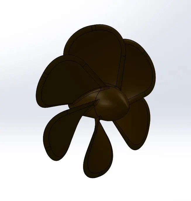
Procedure:
- First the 2D sketch is drawn using sketch feature with appropriate dimensions.
- Then using the Revolve feature the circular model is produced.
- The wing structure is created using surface loft feature and fillets were applied accordingly.
- The rest of the wing structures were produced using the circular pattern.
- Appropriate appearances were applied.
Radar
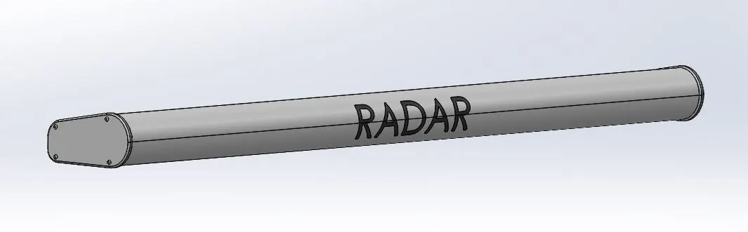
Procedure:
- First the 2D sketch is drawn using sketch feature with appropriate dimensions.
- The solid body is produced using Extrude feature.
- The fillets were applied at required areas.
- Appropriate appearances were applied.
Front Seat
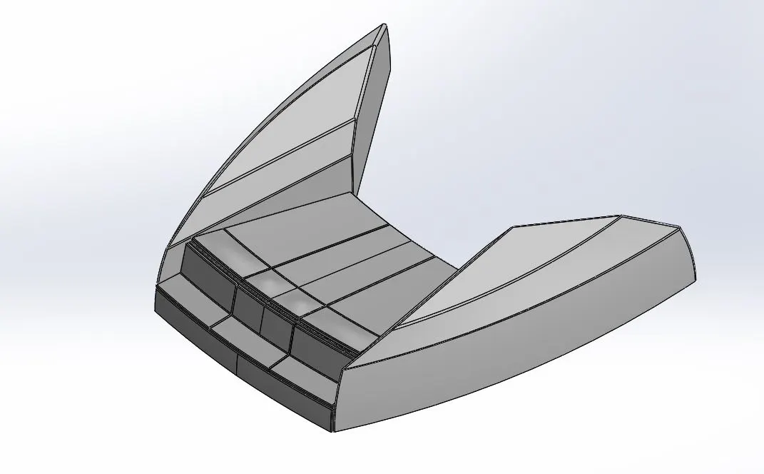
Procedure:
- First the 2D sketch is made using the sketch feature with appropriate dimensions.
- One side of the part is produced using various surface features such as Extruded Surface, Swept Surface, Lofted Surface, Filled Surface, Ruled Surface, Offset Surface, Trim Surface, Extend Surface, Knit Surface.
- By using the mirror feature the other side is generated.
- Fillets were applied at required areas.
- Appropriate appearances were applied.
Middle Seat
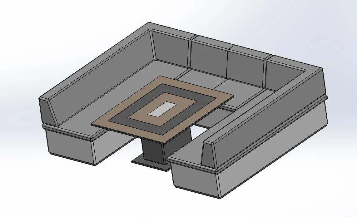
Procedure:
- First the 2D sketch is made using the sketch feature with appropriate dimensions.
- One side of the part is produced using various surface features such as Extruded Surface, Swept Surface, Lofted Surface, Filled Surface, Ruled Surface, Offset Surface, Trim Surface, Extend Surface, Knit Surface.
- By using the mirror feature the other side is generated.
- The table was created using features like Boss Extrude, Cut Extrude.
- Fillets and Chamfers were applied at required areas.
- Appropriate appearances were applied.
Rear Seat
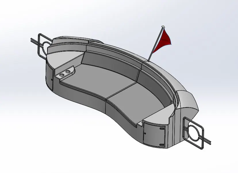
Procedure:
- First the 2D sketch is made using the sketch feature with appropriate dimensions.
- One side of the part is produced using various features such as Boss Extrude, Cut Extrude, Extruded Surface, Swept Surface, Lofted Surface, Filled Surface, Ruled Surface, Offset Surface, Trim Surface, Extend Surface, Knit Surface.
- By using the mirror feature the other side is generated.
- The flagstaff is constructed using Revolve feature.
- The flag was made using splines in the 3D sketch feature.
- Fillets and Chamfers were applied at required areas.
- Appropriate appearances were applied.
Hull
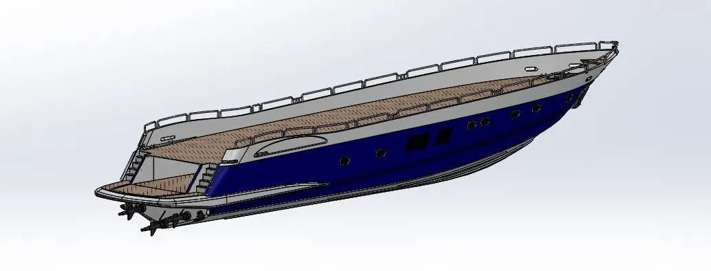
Procedure:
- First the 2D sketch is made using the sketch feature with appropriate dimensions and sketch picture as reference.
- One side of the part is produced using various features such as Boss Extrude, Cut Extrude, Extruded Surface, Swept Surface, Lofted Surface, Filled Surface, Ruled Surface, Offset Surface, Trim Surface, Extend Surface, Knit Surface.
- Some components on the deck were produced using features like Linear pattern, Helix/Spiral, Sweep, Slot.
- Several features were created using the projected curves as reference.
- The Railing reference was built using sweep feature and projected curve as reference.
- By using the mirror feature the other side is generated.
- Fillets and Chamfers were applied at required areas.
- Appropriate decals and appearances were applied.
Garage Door
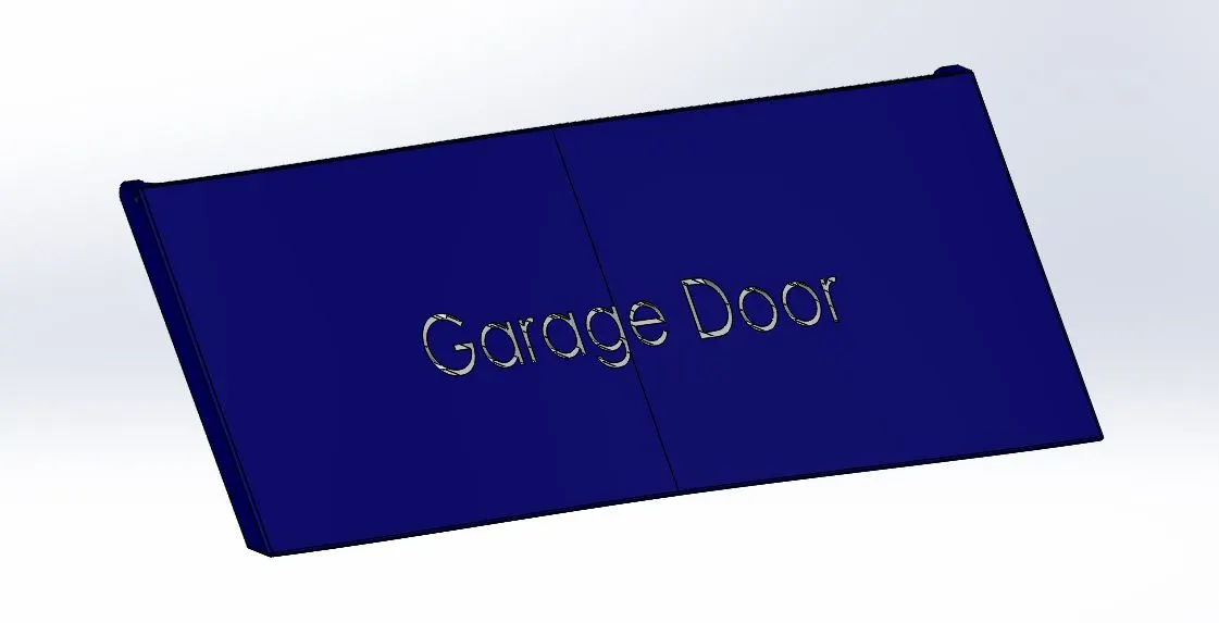
Procedure:
- It is modelled using the truncated part from the Hull.
- First, one side of the part is produced using features such as Cut Extrude, Shell.
- By using the mirror feature the other side is generated.
- Fillets were applied at required areas.
- Text was projected onto the surface & appropriate appearances were applied.
Superstructure
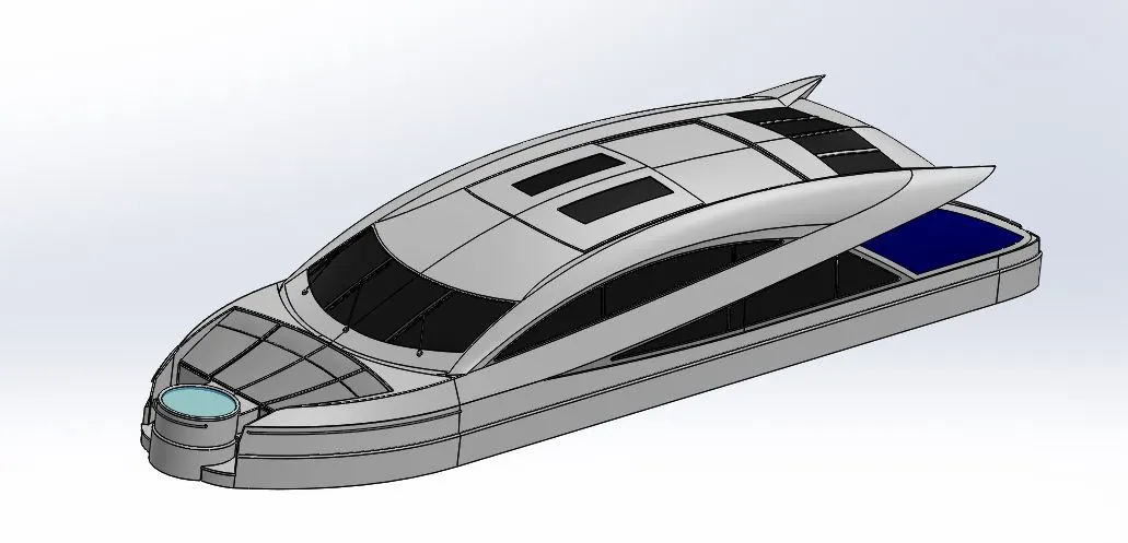
Procedure:
- First the 2D sketch is made on the imported hull deck surface using the sketch feature with appropriate dimensions and sketch picture as reference.
- One side of the part is produced using various features such as Boss Extrude, Cut Extrude, Swept Boss/Base, Extruded Surface, Swept Surface, Lofted Surface, Filled Surface, Ruled Surface, Offset Surface, Trim Surface, Extend Surface, Knit Surface.
- By using the mirror option the other side is generated.
- Fillets and Chamfers were applied at required areas.
- Appropriate appearances were applied.
Radar Mast
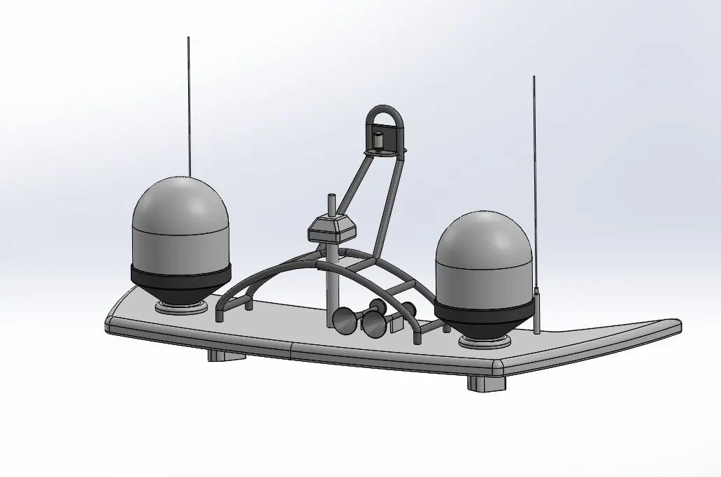
Procedure:
- First the 2D sketch is made on the imported Superstructure Reference surface using the sketch feature with appropriate dimensions and sketch picture as reference.
- The Components of the Radar mast were produced using various features such as Boss Extrude, Fillet, Revolve, Sweep, Projected curve, Chamfer, Dome, Shell and they were mirrored accordingly using the mirror option.
- Appropriate appearances were applied.
Assembly of Yacht
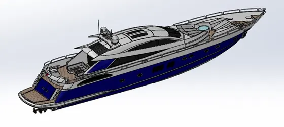
Procedure:
- Import all the parts into the assembly file and click on “ok”, they will automatically get aligned & assembled because appropriate surface references were given while creating various parts of yacht.
- Some parts such as Propeller, Radar, Garage Door needs to be assembled manually using the Concentric mate, Coincident mate features.
Rendering:
The Photo view 360 was enabled in the Add-Ins section of the tools menu. After appropriate settings and desired number of passes the yacht was rendered using PhotoView 360. Below is the rendered image of it.