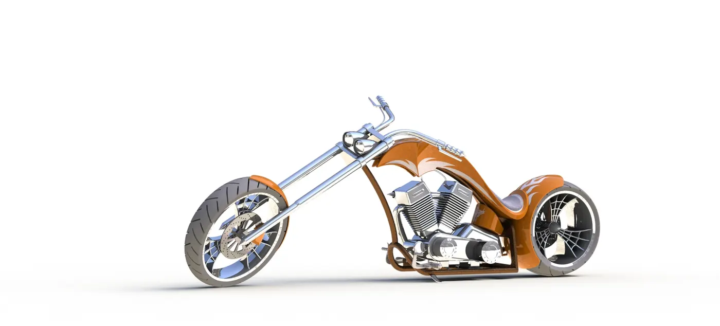
Design, Modelling and Assembly of an American Chopper.
Introduction: All parts of the Chopper were modelled individually and assembled in the SOLIDWORKS 2018 Version.
Objective: To model an American Chopper bike in the SOLIDWORKS software and render it.
Parts that were Modelled:
- Chain
- Chassis
- Engine
- Front fender
- Front fork
- Front wheel
- Gas Tank
- Kickstand
- Oil Tank
- Pedal
- Rear fender
- Rear wheel
- Transmission belt
The following process describes how the above-mentioned parts were built.
Chain
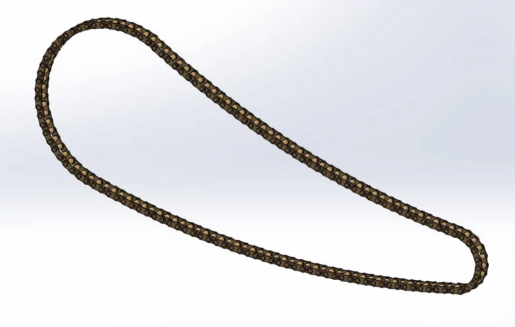
Procedure:
- First the 2D sketch is drawn using sketch feature with appropriate dimensions.
- One side of the chain is produced using features such as Boss/Base Extrude, Fillet, Curve Driven pattern.
- Using the Curve Driven pattern, the outer plates, inner plates and extruded pins were patterned along the sketch.
- Through Mirror feature the other side of chain is produced.
- Appropriate appearances were applied.
Chassis
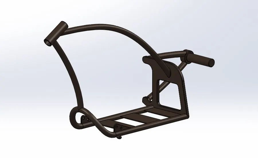
Procedure:
- First the 2D sketch is drawn using sketch feature with appropriate dimensions with reference to the sketch picture & the planes.
- The chassis was built using features such as projected curves, mirror, Boss Extrude, Cut Extrude, Sweep, Dome, Split, Revolve, Combine.
- Fillets, Chamfers were applied at required areas.
- Some sections such as sweep base & pedal holder were mirrored to the other side.
- Appropriate appearances were applied.
Engine
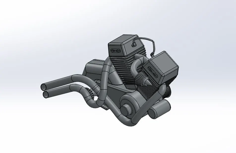
Procedure:
- First the 2D sketch is drawn using sketch feature with appropriate dimensions with reference to the sketch picture & the planes.
- The Engine setup was built using features such as projected curves, mirror, Boss Extrude, Cut Extrude, Sweep, Dome, Split, Revolve, Combine, circular pattern, linear pattern, composite curve.
- One of the engine cylinders was built & mirrored to the other side.
- Fillets & Chamfers were applied at required areas.
- The exhaust pipes were built using the projected curves & composite curve features.
- Appropriate appearances were applied.
Front fender
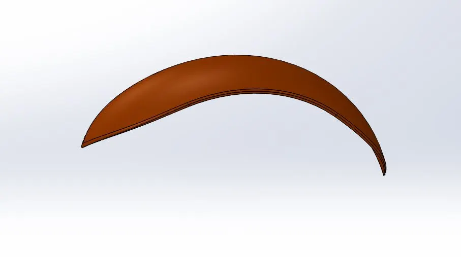
Procedure:
- First the 2D sketch was created with appropriate dimensions with reference to the axis & the planes.
- The sketch was revolved using revolve feature & was cut appropriately using split feature.
- Fillets were applied along the edges.
- Appropriate appearances were applied.
Front fork
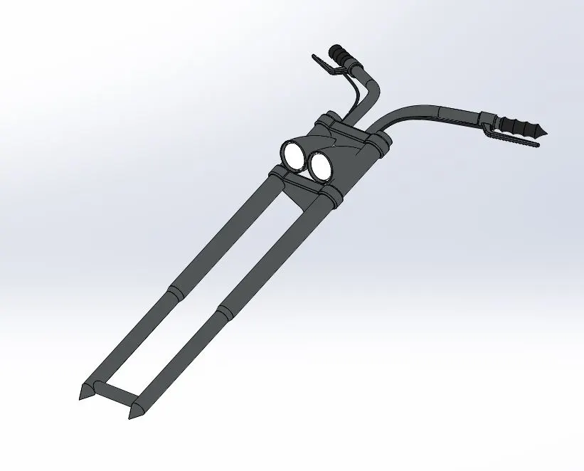
Procedure:
- First the 2D sketch was created with appropriate dimensions with reference to the axis & the planes.
- One side of the part is produced using various features such as Boss Extrude, Cut Extrude, Sweep, Dome, Revolve, Combine, circular pattern, linear pattern, projected curves, Cut Revolve.
- Fillets were applied at required areas.
- Appropriate appearances were applied.
Front wheel
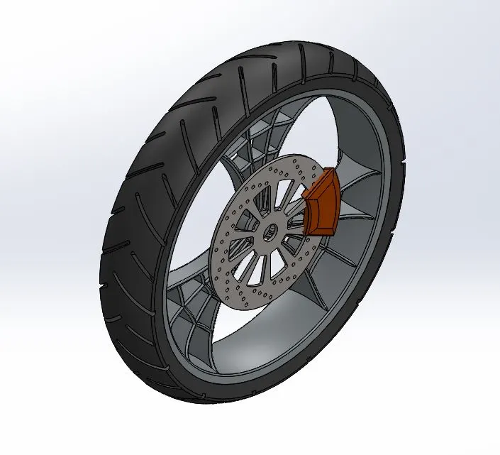
Procedure:
- First the 2D sketch of spider web design of the rim was created carefully with appropriate dimensions.
- The frontwheel was created using features such as Boss Extrude, Cut Extrude, Revolve, Combine, circular pattern, Cut Revolve.
- Fillets and Chamfers were applied at required areas.
- The rotor & caliper were created at proper position.
- Appropriate appearances were applied.
Gas Tank
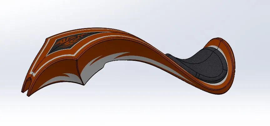
Procedure:
- First the 2D sketch was created using splines with appropriate dimensions with reference to the sketch picture & planes.
- The body of gas tank was built using the features such as Surface sweep, Surface trim, Surface loft, Boundary Surface, Surface knit, split, Surface Extrude, Cut sweep, Shell.
- One side of the gas tank was created and then mirrored to the other side.
- Fillets were applied at required areas.
- Appropriate appearances and decals were applied.
Kickstand
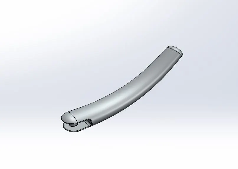
Procedure:
- First the 2D sketch was created using ellipses at the ends. Then using Surface loft feature a solid surface was created along the sketched ellipses.
- The ends were rounded using Dome feature.
- At the bigger end of dome shape, a slit type of cut was made between the upper & lower side.
- A cylindrical structure was created in between them which serves as a joint with the vehicle. The surface of bottom end of smaller dome was made flat using split feature.
- Finally, fillets were applied at required areas.
Oil Tank
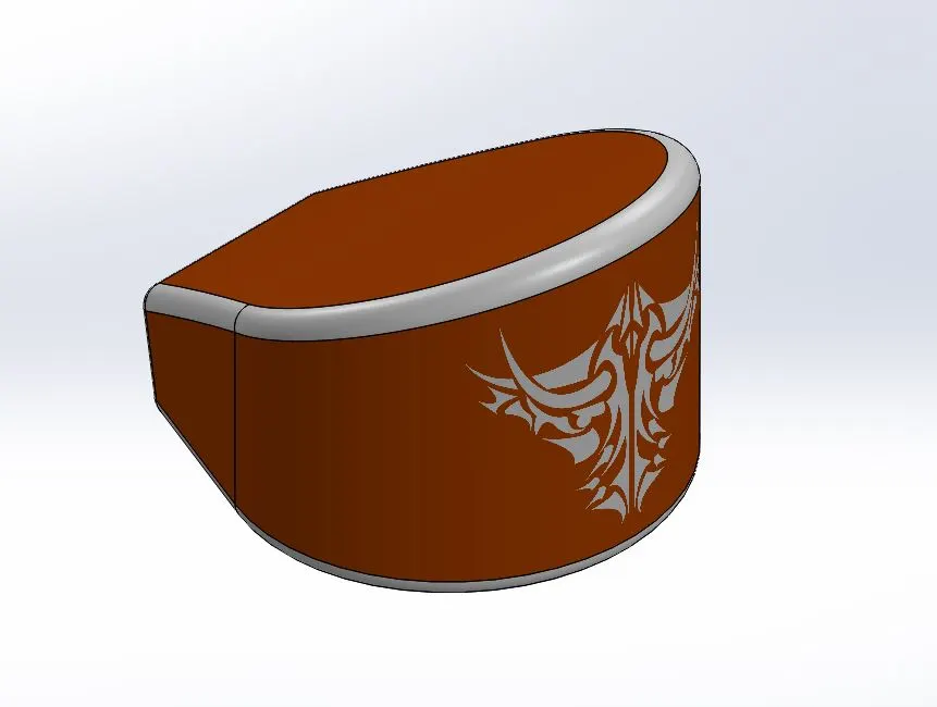
Procedure:
- First the base of the oil tank was 2D sketched using lines and arcs with appropriate dimensions.
- The body oil tank was built using the features such as Boss extrude, Combine, Shell.
- Fillets were applied at required areas.
- Appropriate appearances and decals were applied.
Pedal
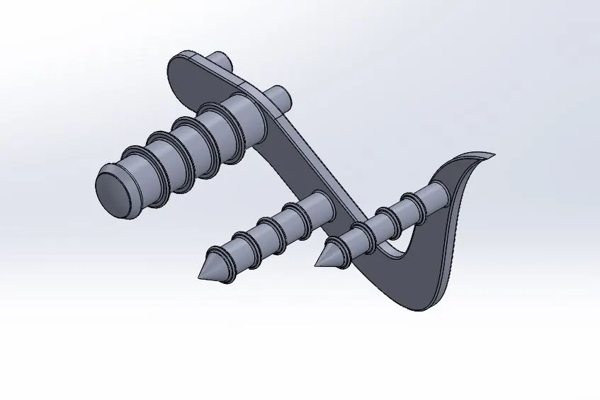
Procedure:
- First the 2D sketch was created using splines, lines & circles with appropriate dimensions with reference to the sketch picture & planes.
- The body of pedal was built using the features such as Boss extrude, Revolve, Dome, Linear pattern.
- Fillets & Chamfers were applied at required areas.
- Appropriate appearances were applied.
Rear fender
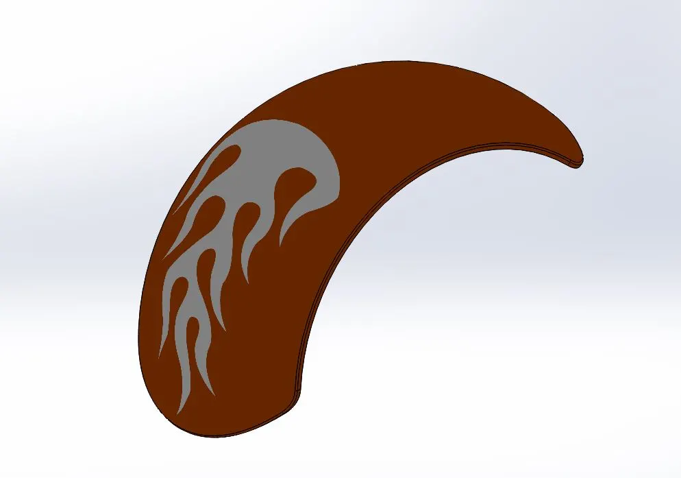
Procedure:
- First the 2D sketch was created with appropriate dimensions with reference to the axis & the planes.
- The sketch was revolved using revolve feature & was cut appropriately using split feature and then shell feature was used.
- Fillets were applied along the edges.
- Appropriate appearances & decals were applied.
Rear wheel
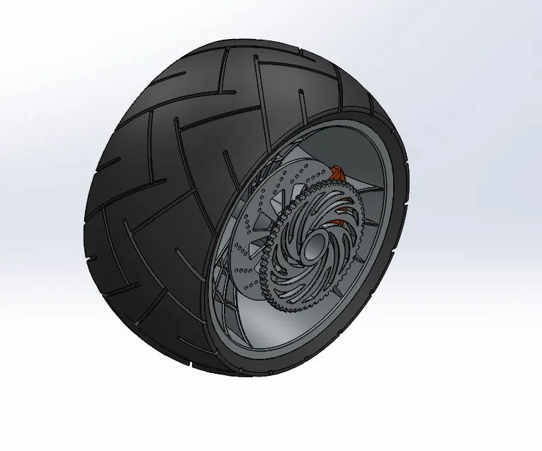
Procedure:
- First the 2D sketch of spider web design of the rim was created carefully with appropriate dimensions.
- The rearwheel was built using features such as Boss Extrude, Cut Extrude, Revolve, Combine, circular pattern, Cut Revolve.
- Fillets and Chamfers were applied at required areas.
- The rotor, caliper & sprocket wheel were created at proper position.
- Appropriate appearances were applied.
Transmission belt
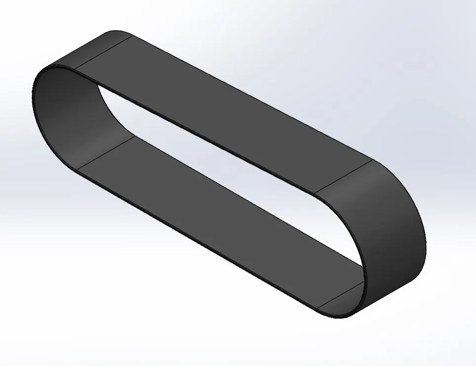
Procedure:
- First the 2D sketch was created using lines & semi circles with appropriate dimensions and then extruded using Boss Extrude feature.
- Fillets were applied along the edges.
American Chopper assembly
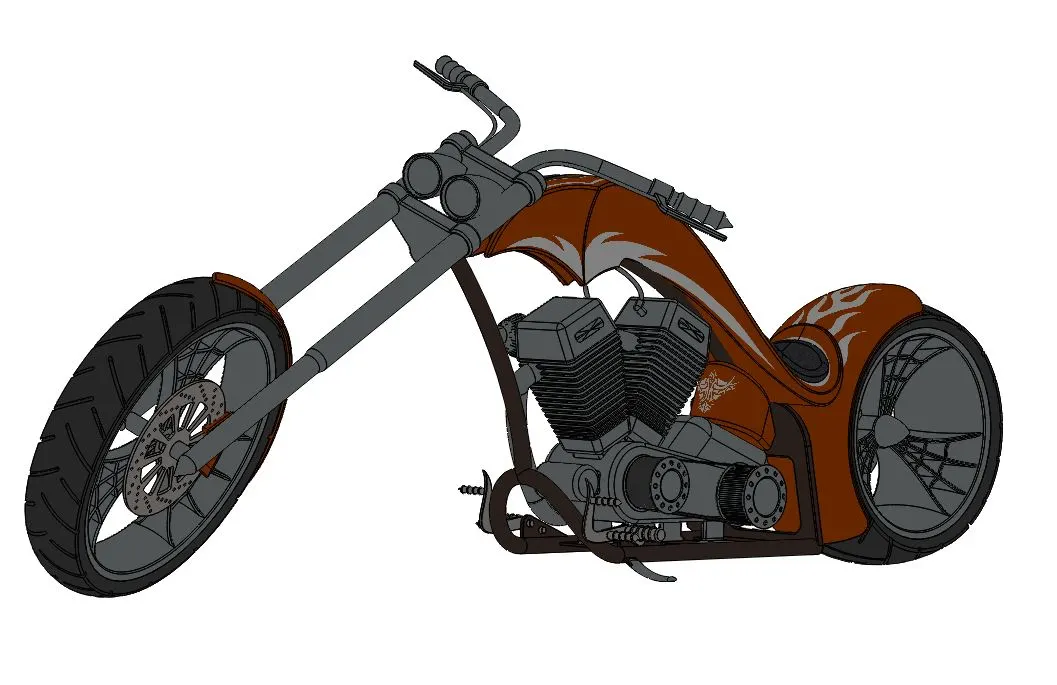
Procedure:
- Open an assembly file & import all the part files into it.
- Then fix the parts manually at appropriate positions using various mates such as Concentric, Coincident, width, angle, distance, parallel, tangent.
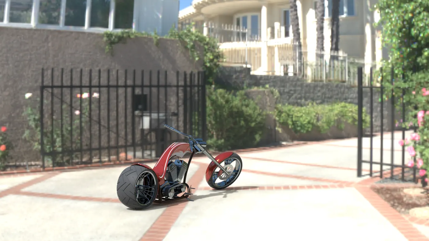
- Now the assembly of the American Chopper was completed and it was rendered using PhotoView 360 & Solidworks Visualize and the images were shown below.